Before energizing following should be checked
1. Voltage rating and polarity.
2. CT circuit rating and integrity of connection.
3. Protective fuse rating.
4. Integrity of the earthing connection.
5. Voltage and current rating of external wiring, applicable as per application.
2.3.1.1 Relay Operating Condition
The equipment should be operated within the specified electrical and environmental limits.
2.3.1.2 Current Transformer (CT) Circuit
Do not open the secondary circuit of a live CT as the high voltage produce may be lethal to personnel
and could damage insulation. For safety, the secondary of the line CT must be shorted before opening
any connection to it.
2.3.1.3 Insulation and Dielectric Strength Testing
Insulation testing may leave capacitors charged up to a hazardous voltage. At the end of each test the
voltage should be gradually reduced to zero to discharge capacitors, otherwise this may result in
damage.
2.3.2 Cables and Connectors
This section describes the type of wiring and connections that should be used when installing the
device. For pin-out details please refer to the wiring diagrams.
Caution: Before carrying out any work on the equipment you should be familiar with the
Safety Section and the ratings on the equipment’s rating label.
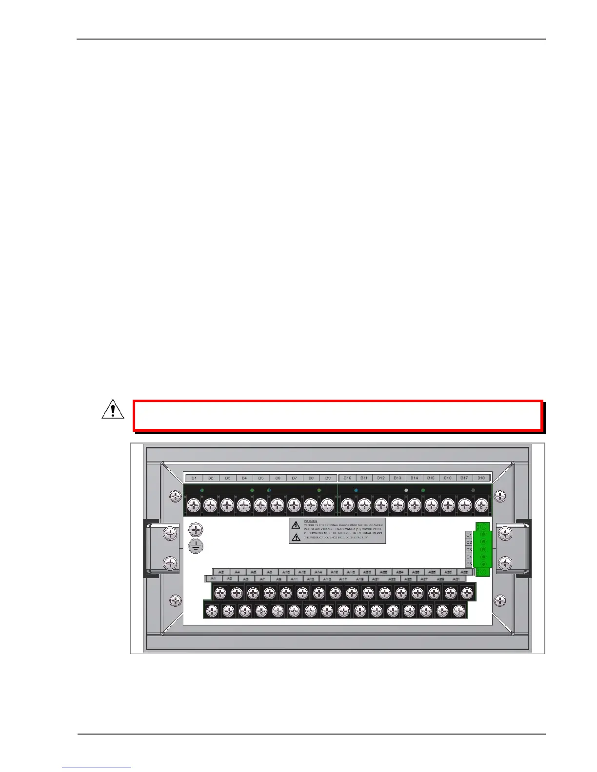
Figure 5: P253 rear view-terminal connection
 Loading...


