If the IED circuit has a very high impedance the secondary current produced by the healthy CT will
flow through the saturated CT. If CT magnetising impedance of the saturated CT is considered to be
negligible the maximum voltage across the circuit will be equal to the secondary fault current multiplied
by the connected impedance, (RL3 + RL4 + RCT2).
The IED can be made stable for this maximum applied voltage by increasing the overall impedance of
the circuit, such that the resulting current through it is less than its current setting. As the impedance of
the IED input alone is relatively low, a series connected external resistor is required. The value of this
resistor, RST, is calculated by the formula shown. An additional non-linear, Metrosil, may be required
to limit the peak secondary circuit voltage during internal fault conditions.
Voltage across REF element Vs = IF (RCT2 + RL3 + RL4)
Stabilising resistor RST = Vs/Is –RR
where:
• I
F = maximum secondary through fault current
• R
R = device burden
• R
CT = CT secondary winding resistance
• R
L2 and RL3 = Resistances of leads from the device to the current transformer
• R
ST = Stabilising resistor
To ensure that the protection will operate quickly during an internal fault the CTs used to operate the
protection must have a knee-point voltage of at least 4 Vs.
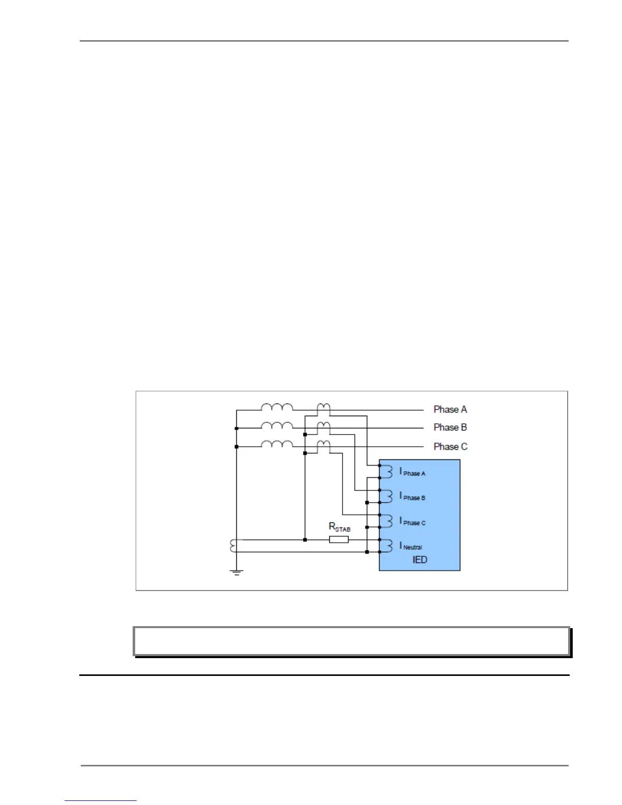
The necessary connections for high impedance REF are as follows:
Figure 10: High Impedance REF connection
Note: The starting current or locked rotor current value in motors is usually used in the stability calculation.
This will lead to relatively small CT requirements.
2.10 Loss of Load Protection Function
The relay includes undercurrent elements that can be used to provide additional functions to prevent
damage to the power system. This function allows typical applications such as loss of load. The
undercurrent protection function is available only if the auxiliary contact of the CB status is connected
 Loading...


