2.4.3 Timer Hold Facility/Reset Characteristics
This feature may be useful in certain applications, such as when grading with upstream
electromechanical overcurrent relays, which have inherent reset time delays. If you set the hold timer
to a value other than zero, the resetting of the protection element timers will be delayed for this period.
This allows the element to behave in a similar way to an electromechanical relay. If you set the hold
timer to zero, the overcurrent timer for that stage will reset instantaneously as soon as the current falls
below a specified percentage of the current setting (typically 95%).
Another possible situation where the timer hold facility may be used to reduce fault clearance times is
for intermittent faults. An example of this may occur in a plastic insulated cable. In this application it is
possible for the fault energy to melt and reseal the cable insulation, thereby extinguishing the fault.
This process repeats to give a succession of fault current pulses, each of increasing duration with
reducing intervals between the pulses, until the fault becomes permanent.
When the reset time is instantaneous, the device will repeatedly reset and not be able to trip until the
fault becomes permanent. By using the Timer Hold facility the device will integrate the fault current
pulses, thereby reducing fault clearance time.
The timer hold facility is available to all three stages of OC and EF functions.
The Definite Time Reset characteristic is applicable for IEC curves / DT.
The value of the Reset Timer depends on the type of the timer associated to the pick-up phase (Earth)
threshold.
Type of timer associated with phase (earth)
- For IDMT IEEE or CO time delay 0 – 100 sec Based on RTMS value
(0.025-1.2)
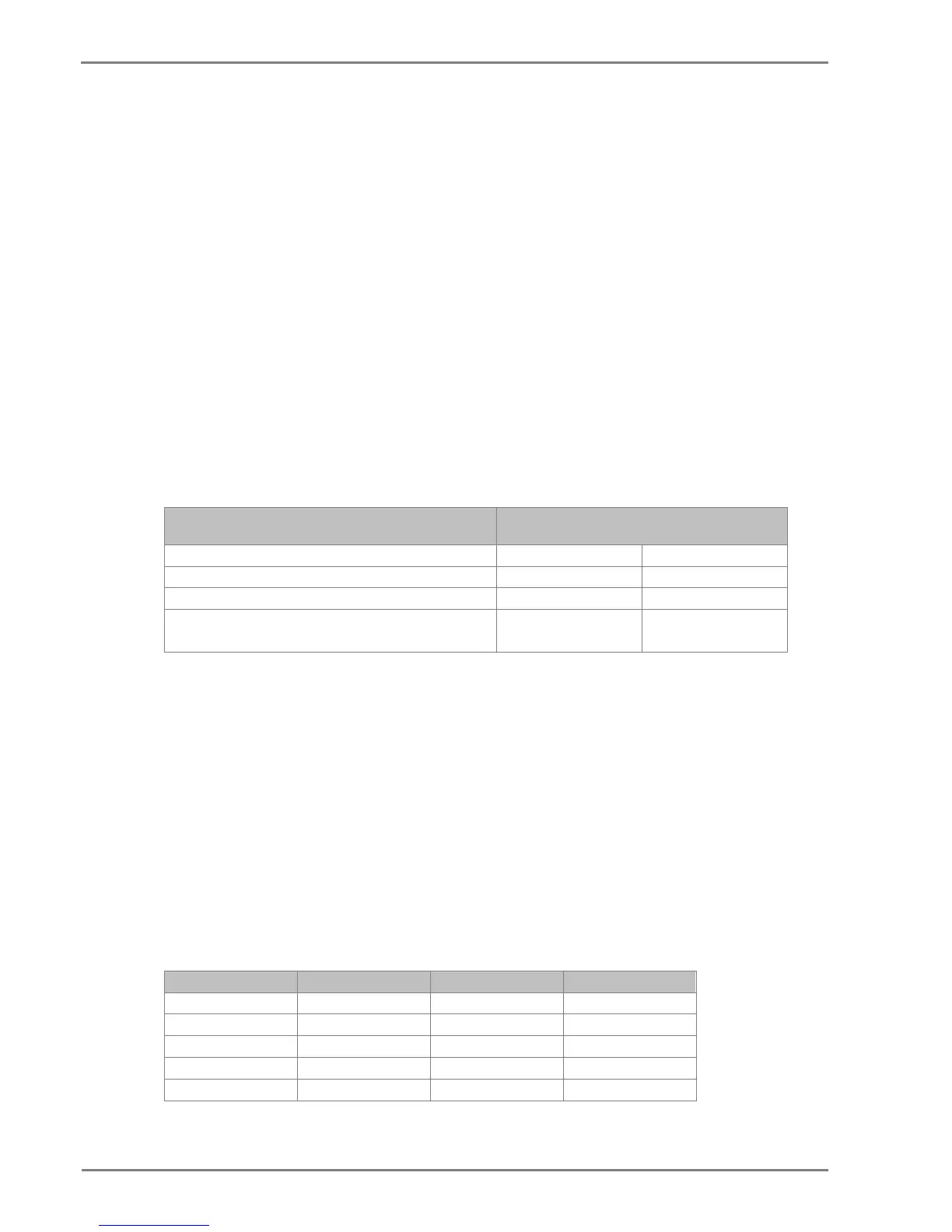
The mathematical formula applicable to the five curves is:
t = RTMS x K
--------------------
1- (I / Is)
α
Where:
t = Reset time
K = Factor (see table)
I = Value of the measured current
Is = Value of the programmed threshold (pick-up value)
α = Factor (see table)
RTMS Reset time multiplier (RTMS) setting is between 0.025 and 1.2
Description Standard K α
Moderate Inverse IEEE 4.85 2
Very Inverse IEEE 21.6 2
 Loading...


