2.3.3.4 Earth Connection
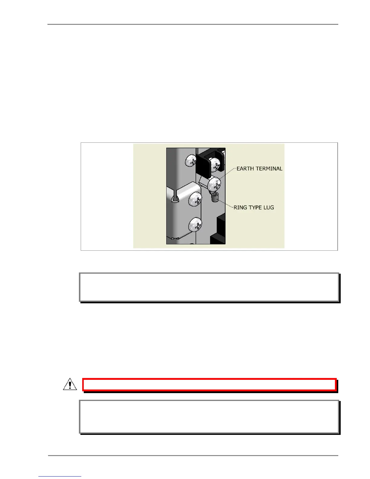
Every device must be connected to the cubicle earthing bar. Earthing terminal is provided on the back
of the relay. Ensure that the relay earthing is connected to the local earth bar. With several relays
present; make sure that the copper earth bar is properly installed for solidity connecting to the earthing
terminal of each relay equipment box.
Before energizing the equipment it must be earthed using the protective conductor terminal, (if
provided) or the appropriate termination of the supply plug in the case of plug connected equipment.
The protective conductor (earth) connection must not be removed since the protection against electric
shock provided by the equipment would be lost. The recommended minimum protective conductor
(earth) wire size is 2.5 mm² or as per industries standard practice. The protective conductor (earth)
connection must be of low-inductance and as short as possible.
Figure 8: Earthing terminal on the rear side of the relay
Note: To prevent any possibility of electrolytic action between brass or copper ground conductors and the
rear panel of the product, precautions should be taken to isolate them from one another. This could
be achieved in several ways, including placing a nickel-plated or insulating washer between the
conductor and the product case, or using tinned ring terminals.
2.3.3.5 Current Transformers
Current transformers are generally wired with 2.5 mm
2
PVC insulated multi-stranded copper wire
terminated with M5 ring terminals. The wires should be terminated with rings using 90º rings terminals,
with no more than two rings per terminal.
Due to the physical limitations of the ring terminal, the maximum wire size you can use is 4.0 mm
2
using ring terminals.
The wire should have a minimum voltage rating of 300 V RMS.
Caution: Current transformer circuits must never be fused.
Note 1: Terminal blocks must not be detached while any current transformer (CT) circuit is live. CT shorting
must be achieved by external means as the product does not include this facility.
Note 2: For 5A CT secondary, we recommend using 2 x 2.5 mm
2
PVC insulated multi-stranded copper wire.
 Loading...


