– 67 –
Cooktop Elements
Induction Elements
Each induction element consists of a coil and a
sensor. The resistance value of the coil is less than
1 Ω at room temperature. The resistance value of
the sensor is 1000 at room temp (+ or -10%). The
sensor has a positive coeffi cient. As the temperature
increases, the sensor's resistance increases.
The sensor and coil are replaced as a complete
assembly. Each element has 4 guides, 2 of which
are held in place with a split pin that is permanently
attached to the aluminum plate.
To remove induction elements:
1. Remove the aluminum plate. (See Aluminum
Plate.)
2. Place the aluminum plate element side up on a
protective surface.
3. Mark the alignment pins and guides for correct
replacement.
Caution: To prevent damage to element insulation,
care should be taken when handling an element.
Note: If some insulation should separate from the
element, it can be placed back on the element in its
original position. Do not use any adhesives.
4. Carefully place a fl at blade screwdriver under a
guide that is captured by a pin.
5. Slowly pry upward and release the element off
the pin.
6. Lift the released side of the element vertically
until disengaged from the opposite pin.
8. Note the routing of the element wires, and
loosen the 2 slotted T-25 Torx screws holding
the element wires to the generator board.
Note
• The element wire terminals are forked and can
be removed without completely removing the
screws.
• The individual wires from each element have no
polarity and can be connected to either of the
screw posts for that specifi c element.
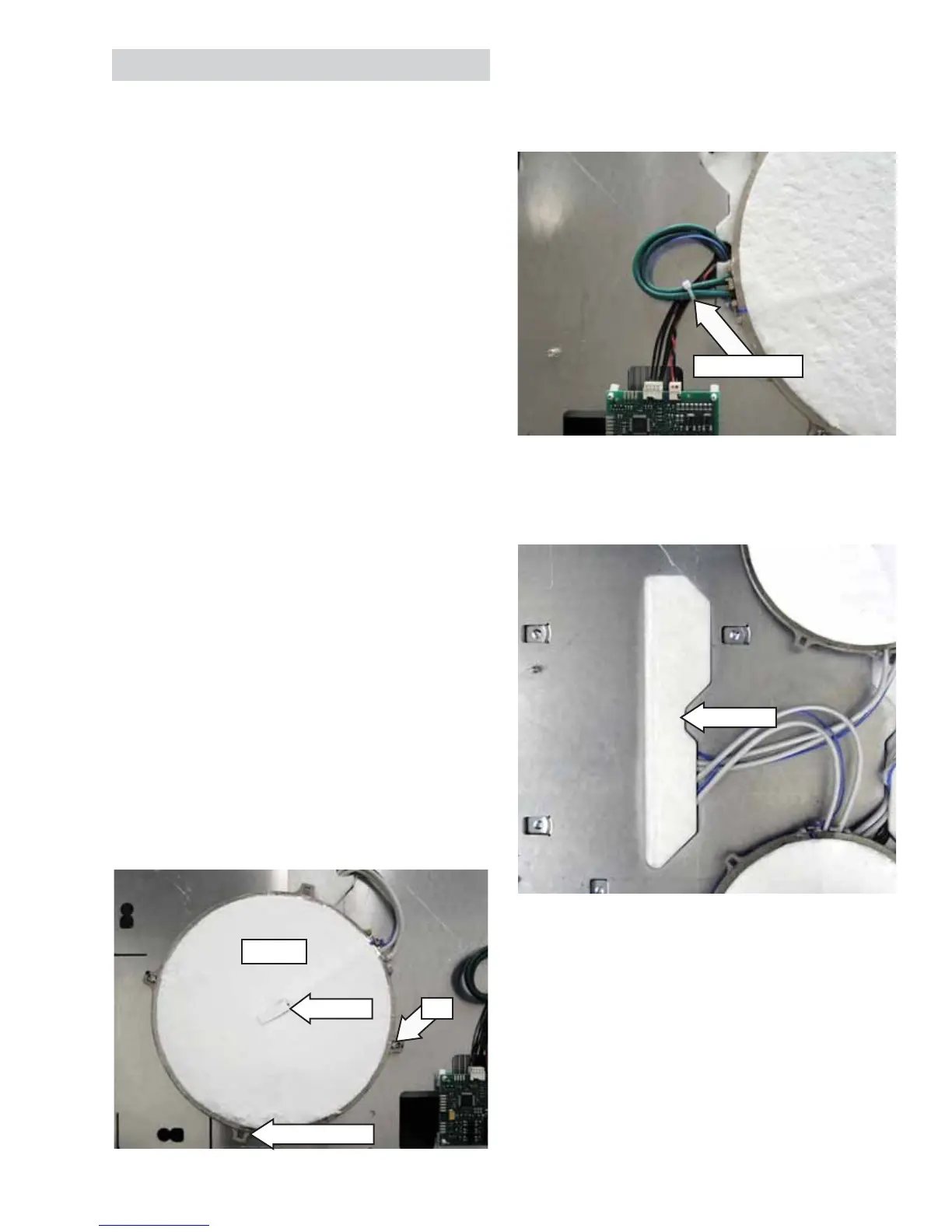
7. Lift and fold back the insulation from the wire
entry in the aluminum plate.
Sensor
Guide (1 of 4)
Pin
Element
Insulation
(Continued next page)
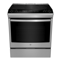
Note: Replacing the 11-in. element will require
cutting off and replacing the plastic wire tie joining
bridge board wiring and element wiring.
Plastic Wire Tie
 Loading...