– 69 –
LINbus Connectors
Caution: To prevent damage to LINbus (Local
Interconnect Network bus) connections, properly
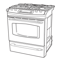
use (as shown below) a Molex 69008-1070 tool when
removing LINbus connectors.
Note: A Molex 69008-1070 tool will be provided with
any part that requires the LINbus connectors to be
removed.
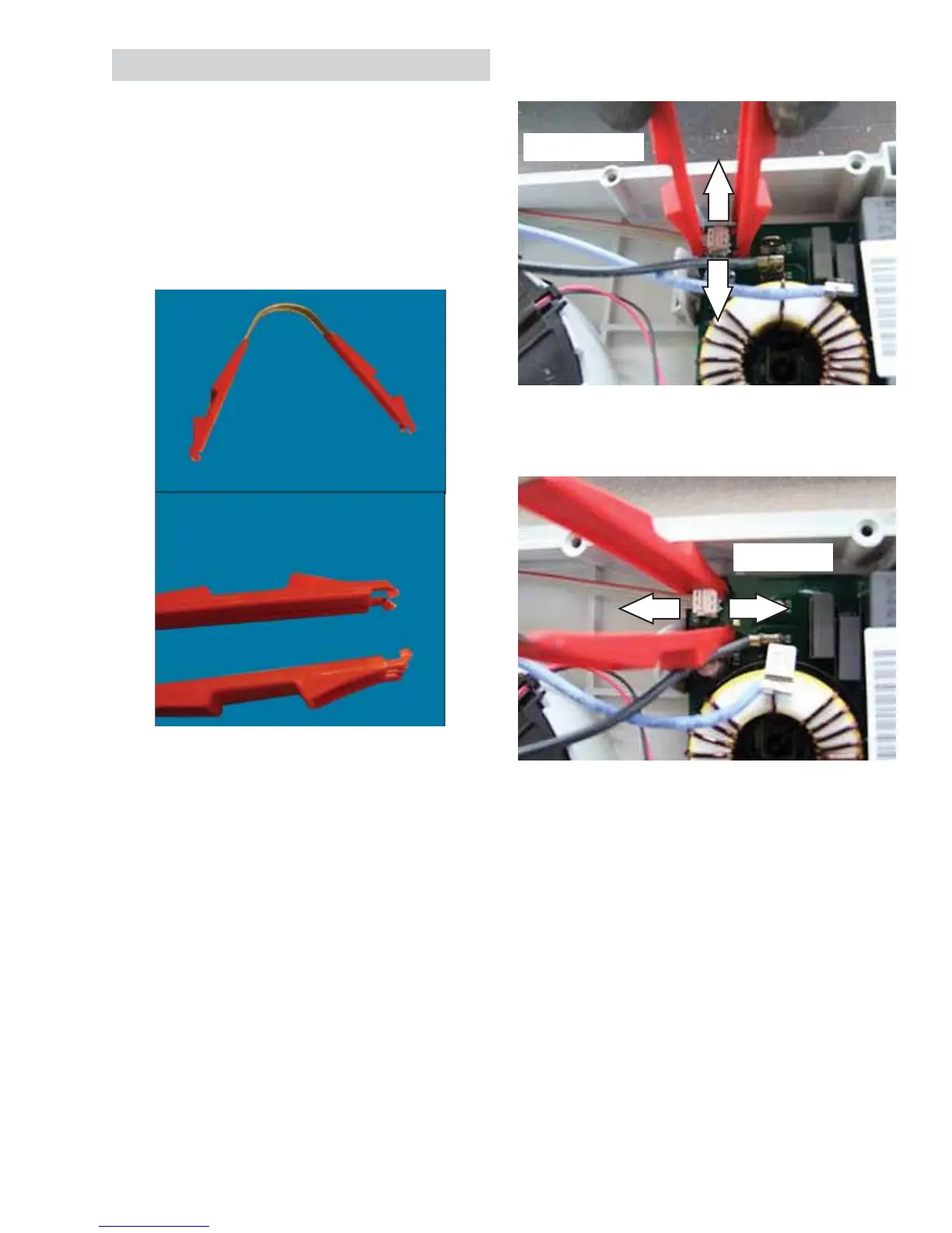
INCORRECT
Do not use front-to-back motion to remove LINbus
connector.
Molex 69008-1070 Tool
Correct way: Use side-to-side motion to remove the
LINbus connector.
Note
• LINbus is a communication network comprised
of a LIN master and 1 or more LIN slaves. The
main logic board acts as the LIN master while
the RPSM, bridge, fi lter, and generator boards
are the LIN slaves.
• All of these components receive a signal to
perform a specifi c task, but only the appropriate
component will act on the message and
respond accordingly. The component that acts
on the specifi c task is based on programming.
Since the LINbus signal is a digital control signal,
special equipment, such as an oscilloscope, is
required to measure it.
CORRECT
 Loading...