– 71 –
Generator Boards
To remove the generator boards:
1. Remove the induction module. (See
Induction
Module
.)
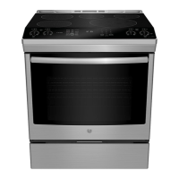
Note: The heat sinks on the right and left generator
boards are joined together with 2 metal clips. The
clips must be removed to replace either generator
board.
2. If applicable, use a small fl at blade screwdriver
to pry up and remove the 2 heat sink clips.
Clip
Clip
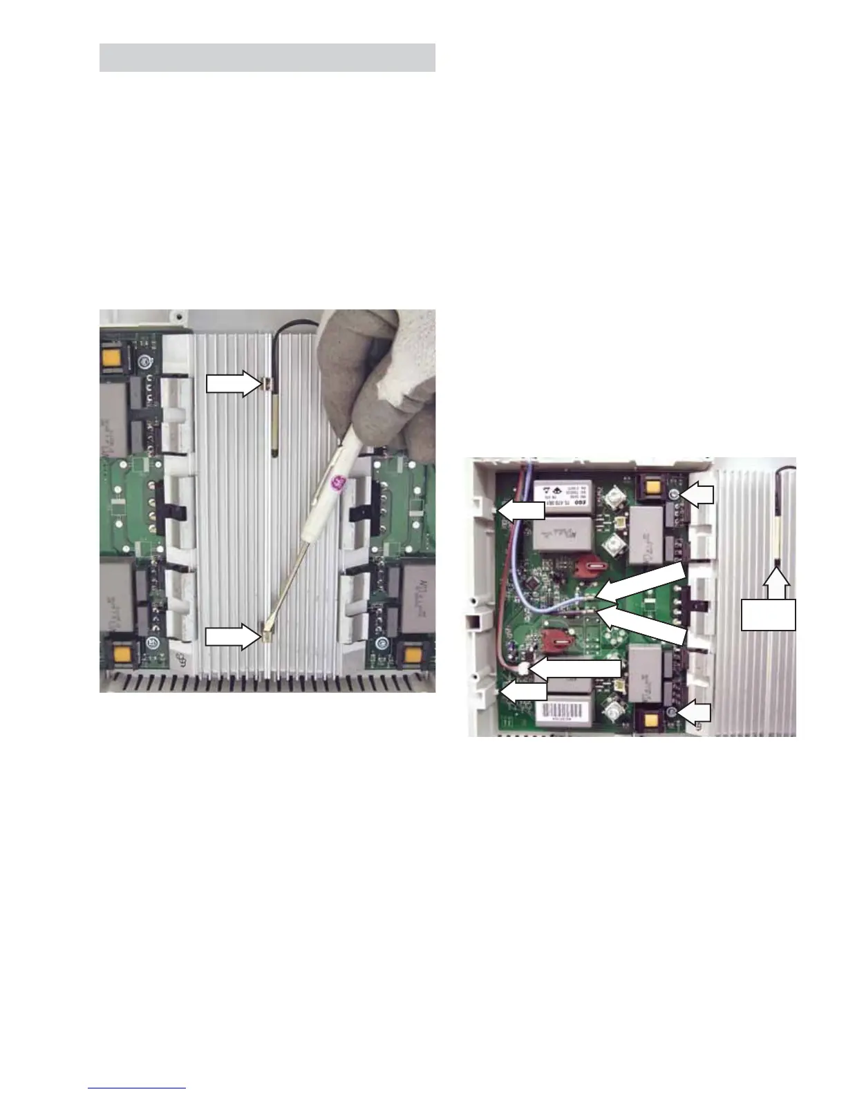
3. Mark the location of the black L1 and the blue L2
wires and disconnect both from the generator
board.
Note: When replacing the L1 and L2 wiring
connecting the fi lter board to the generator board,
connect that wiring in a matching confi guration. For
example, if the L1 output is connected to the bottom
terminal on the fi lter board, it must be connected to
the bottom terminal on the generator board.
4. Disconnect the LINbus connector. (See LINbus
Connectors.)
5. Note the position of the thermal cut out and pull
it out of the heat sink fi ns.
Disconnect
Disconnect
Thermal
Cut Out
Tab
Tab
Disconnect
6. Remove the two T-15 Torx screws that hold the
generator to the module base.
7. Lift the heat sink side and slide the generator
board away from the 2 tabs on the module
base.
 Loading...