80224_MHW_650 L - 1250 L_07-2018_ENG - 15
2.2.5. Connecting inputs and outputs
To prevent noise, the instrument’s input and output wiring
must be kept away from the power cables (high voltages or
high currents).
The input and output cables and the power cables must not
be placed parallel to one another.
Use shielded cables or separate cable trays.
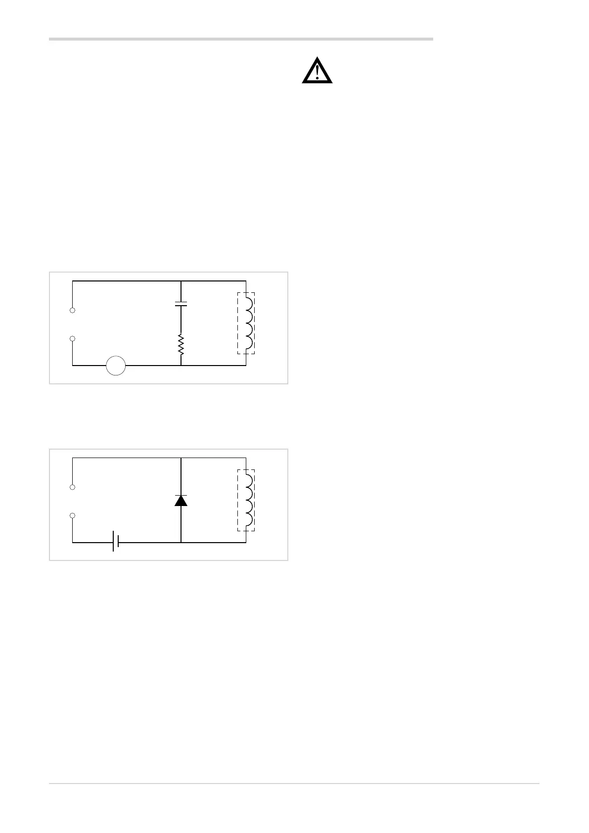
To connect the output to an inductive load (relay, contactor,
valve, motor, fan, solenoid, etc.) that works in AC, mount a
snubber, i.e., an RC group (resistor and condenser in series)
placed parallel to the load. Installing this filter lengthens the
life of the relays.
NOTE: All condensers must conform to VDE (class X2) stan-
dards and support voltage ≥ 220 VAC.
The power of the resistor must be ≥ 2 W.
~
Out
R
C
L
Figure 8 - Snubber connection diagram (AC)
For inductive loads that work in DC, mount a 1N4007 diode
parallel to the coil.
Out LD
+ -
Figure 9 - Snubber connection diagram (DC)
The filters must be connected as close as possible to the
instrument.
Attention! If the instrument is connected to devi-
ces that are NOT electrically isolated (such as ther-
mocouples), ground with a separate conductor to
prevent grounding directly through the machine
structure.
2. INSTALLATION

 Loading...