12
APT4000PH
Installation and connection
Information on installation
Caution!
• The analyzer may only be installed by trained experts
in accordance with this instruction manual
and as per applicable local and national codes.
• Be sure to observe the technical specifications and
input ratings.
• Be sure not to notch the conductor when stripping the
insulation.
• Before connecting the analyzer to the power supply,
make sure that its voltage lies within the range
20.5 to 253 V AC/DC.
• When commissioning, a complete configuration must be
carried out by the system administrator.
The terminals are suitable for single wires and flexible leads up to
2.5 mm
2
(AWG 14).
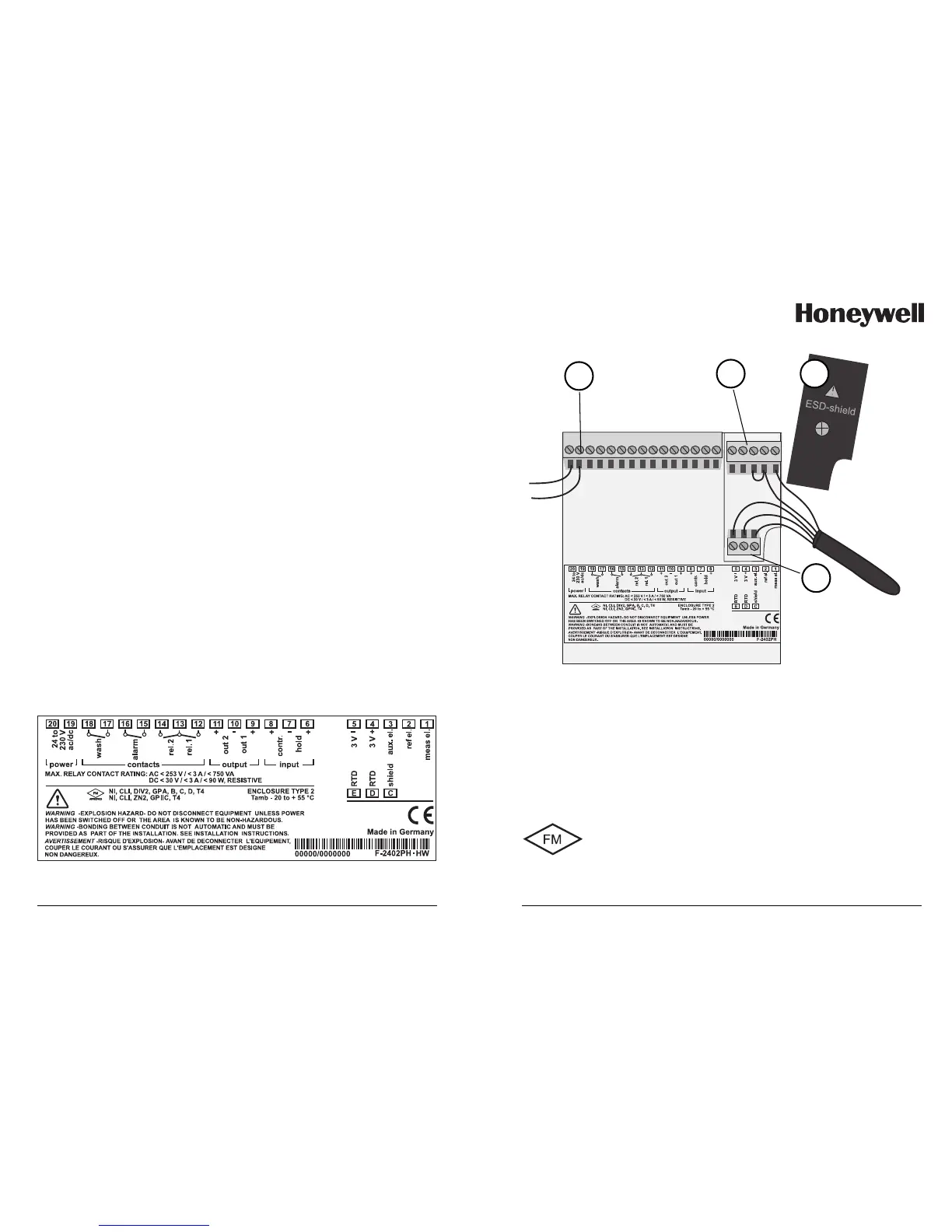
Terminal assignments
Fig. 6: Terminal assignments APT4000PH
13
1 ESD shield covering the signal inputs (Screw off for assembly)
Note: The cable shield must end under the ESD shield.
(Cut lines if required)
2 Terminals for temperature probe and outer shield
3 Terminals for electrode
4 Connection of power supply
Fig. 7: Information on installation, rear side of analyzer
1
3
2
4
The connections to the analyzer are incendive and
must be installed in accordance with the National
Electric Code (ANSI-NFPA 70) Division 2 hazardous
(classified) location incendive wiring techniques.
Division 2 wiring

 Loading...


