4. Press CFREQUENCY] to activate center frequency. Turn the knob clockwise slowly to adjust
the center frequency until a second signal peak is placed at the position of the second
marker. It may be necessary to pause occasionally while turning the knob to allow a sweep
to update the trace. The first marker remains on the screen at the amplitude of the first
signal peak.
Note
Changing the reference level changes the marker delta amplitude readout.
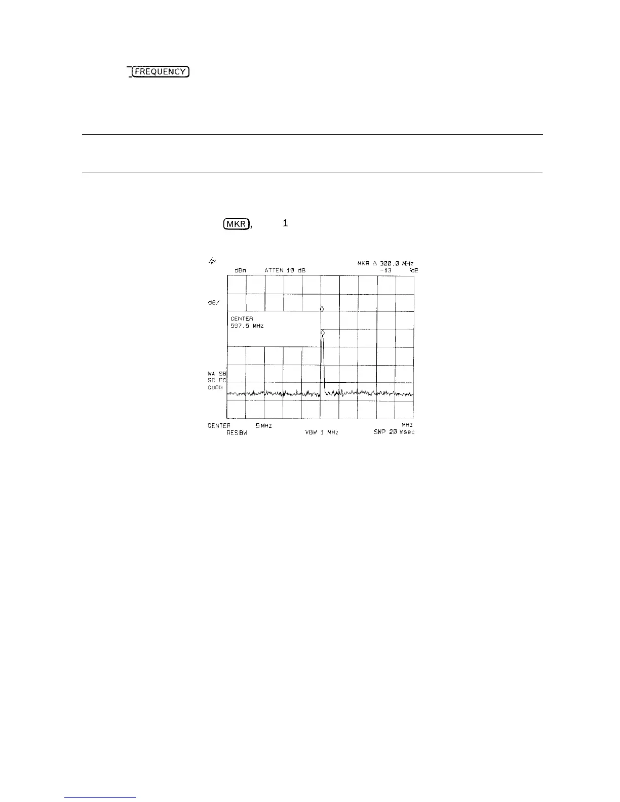
The annotation in the upper-right corner of the screen indicates the amplitude and frequency
difference between the two markers. See Figure 3-15.
To turn the markers off, press
IIVIKR),
More
1
of 2 , then MARKER ALL OFF .
~
-
““7
3
h
MKR
A
306.~
,mn
REF 0
dBm
ATTEN
10
dB
-13
33 dL
PEAK
LOG
10
d8/
CEIlTER
597 5 MHz
SPAN 500.0
MHz
RES
EW
3 MHZ
VEW
1
MHZ
SWP
28
msec
Figure 3-15. Frequency and Amplitude Difference between Signals
3-14 Making Basic Measurements
 Loading...


