Making Reflection Calibration Measurements
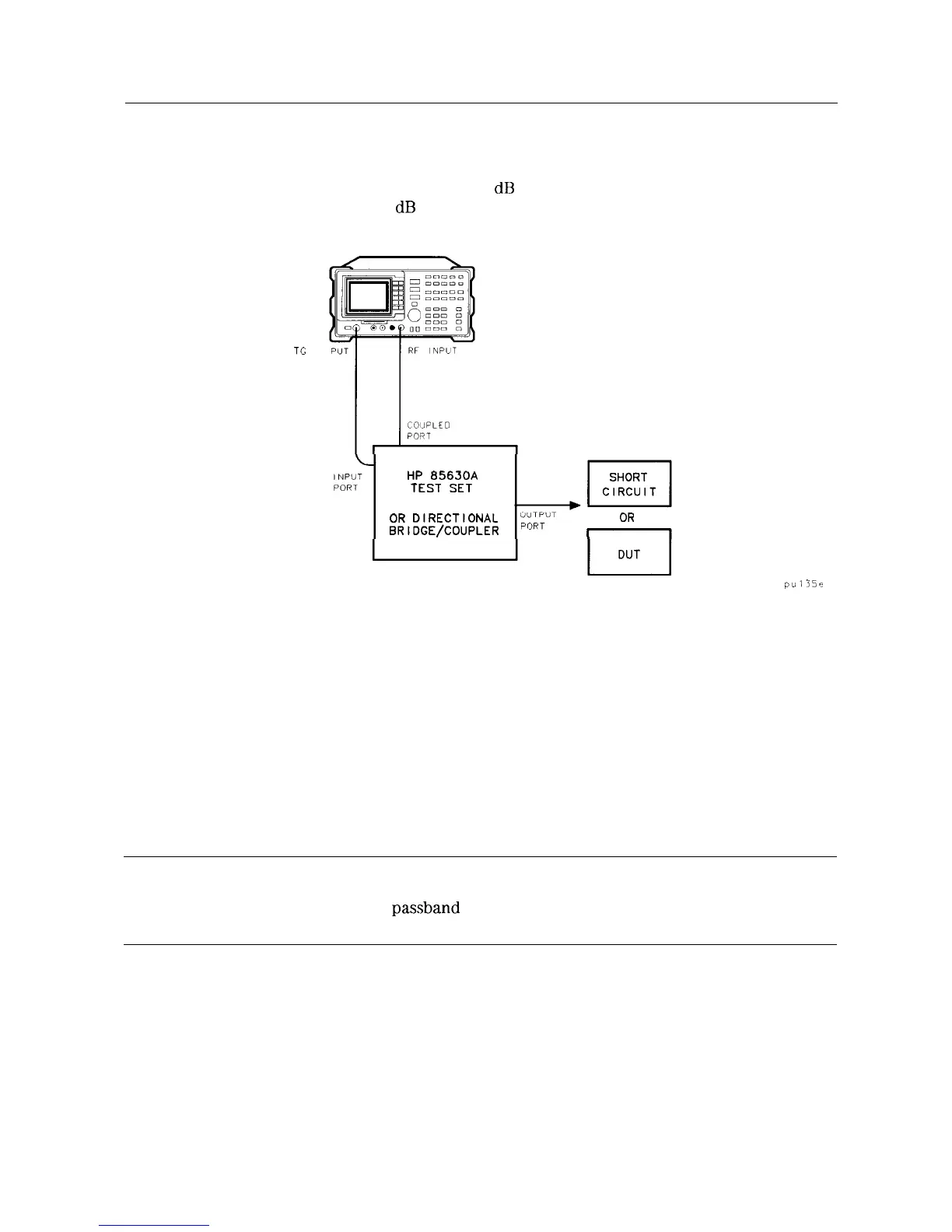
Typically, the calibration standard for reflection measurements is a short circuit connected at
the reference plane (the point at which the test device will be connected-see Figure 4-15).
A short circuit has a reflection coefficient of 1 (0
dB
return loss); it thus reflects all incident
power and provides a convenient 0
dB
reference.
TC OUT
HP
85630A
TEST
SET
OR
DIRECTIONAL
OR
BRIDGE/COUPLER
pu135e
Figure 4-15. Reflection Measurement Short Calibration Test Setup
Example: Measure the return loss of a filter.
The HP 85630A transmission/reflection test set is recommended for making reflection
measurements with your spectrum analyzer. It must be used with the HP 85714A scalar
measurement personality. The scalar measurement personality includes instructions on how
to make fast, accurate scalar network analysis measurements with your spectrum analyzer
and test set. The following procedure is written for making a reflection measurement using a
coupler or directional bridge, instead of the test set.
Reflection Calibration
Note
The spectrum analyzer center frequency and span for this measurement can
easily be set up using the transmission measurement setup. Tune the spectrum
analyzer so that the
passband
of the filter comprises a majority of the display,
then proceed with the steps outlined below.
1. Connect the DUT to the output port of a directional bridge or coupler. Terminate the
unconnected port of the DUT.
2. Connect the tracking generator output of the spectrum analyzer to the input port of a
directional bridge or coupler.
3. Connect the spectrum analyzer INPUT to the coupled port of a directional bridge or coupler.
Making Measurements 4-17
 Loading...


