12 SERVICE WORK ON THE CHASSIS 45
C00567-11
– Remove O-ring
4
. Remove protective ring
5
.
– Take off the lower triple clamp with the steering stem.
– Remove the upper steering head bearing.
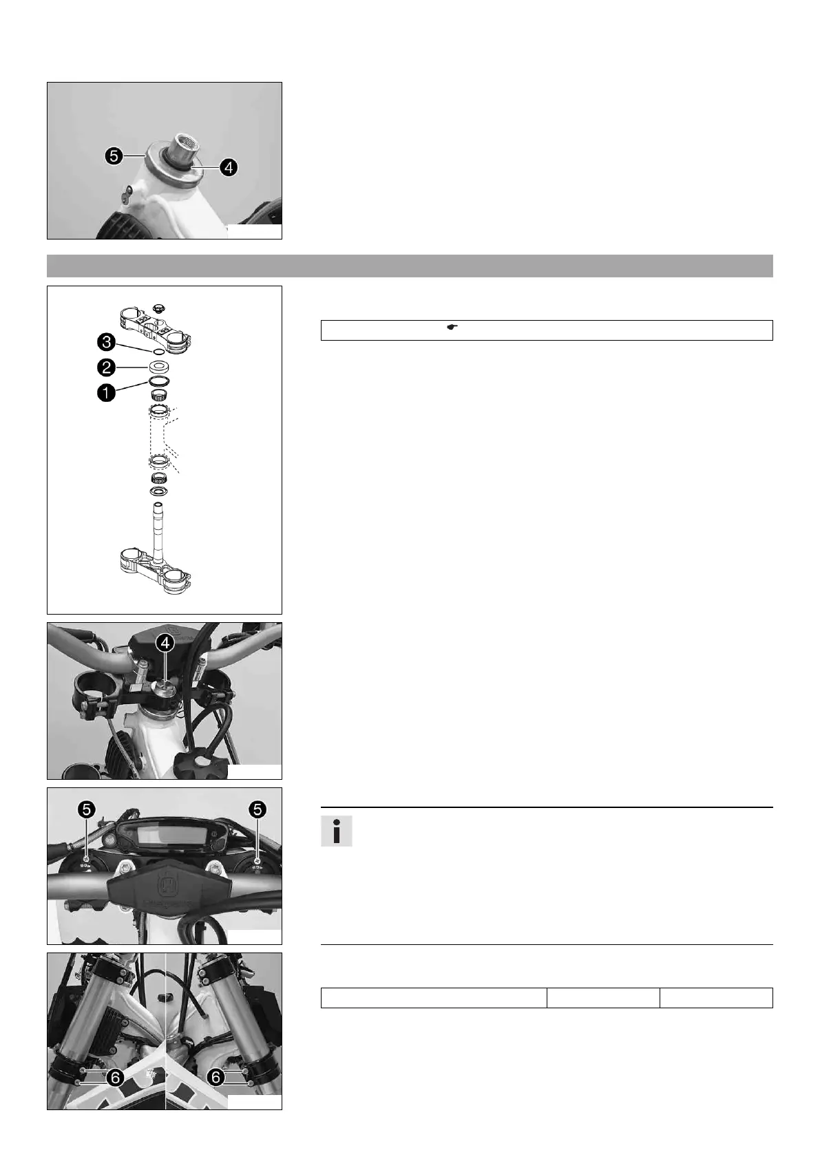
12.12 Installing the lower triple clamp x
B01632-10
Main work
– Clean the bearing and sealing elements, check for damage, and grease.
High viscosity grease ( p. 110)
– Position the lower triple clamp with the steering stem. Mount the upper steering head
bearing.
– Check whether the top steering head seal
1
is correctly positioned.
– Mount protective ring
2
and O-ring
3
.
C00585-10
– Position the upper triple clamp with the steering.
– Mount screw
4
but do not tighten yet.
– Position the clutch line next to the voltage regulator.
C00598-10
– Position the fork legs.
Info
The compression damping is located in the left fork leg COMP (white adjust-
ing screw). The rebound damping is located in the right fork leg REB (red
adjusting screw).
Grooves are milled into the side of the upper end of the fork legs. The sec-
ond milled groove (from the top) must be flush with the top edge of the upper
triple clamp.
Position bleeder screws
5
toward the front.
C00586-10
– Tighten screws
6
.
Guideline
Screw, bottom triple clamp M8 15 Nm (11.1 lbf ft)

 Loading...