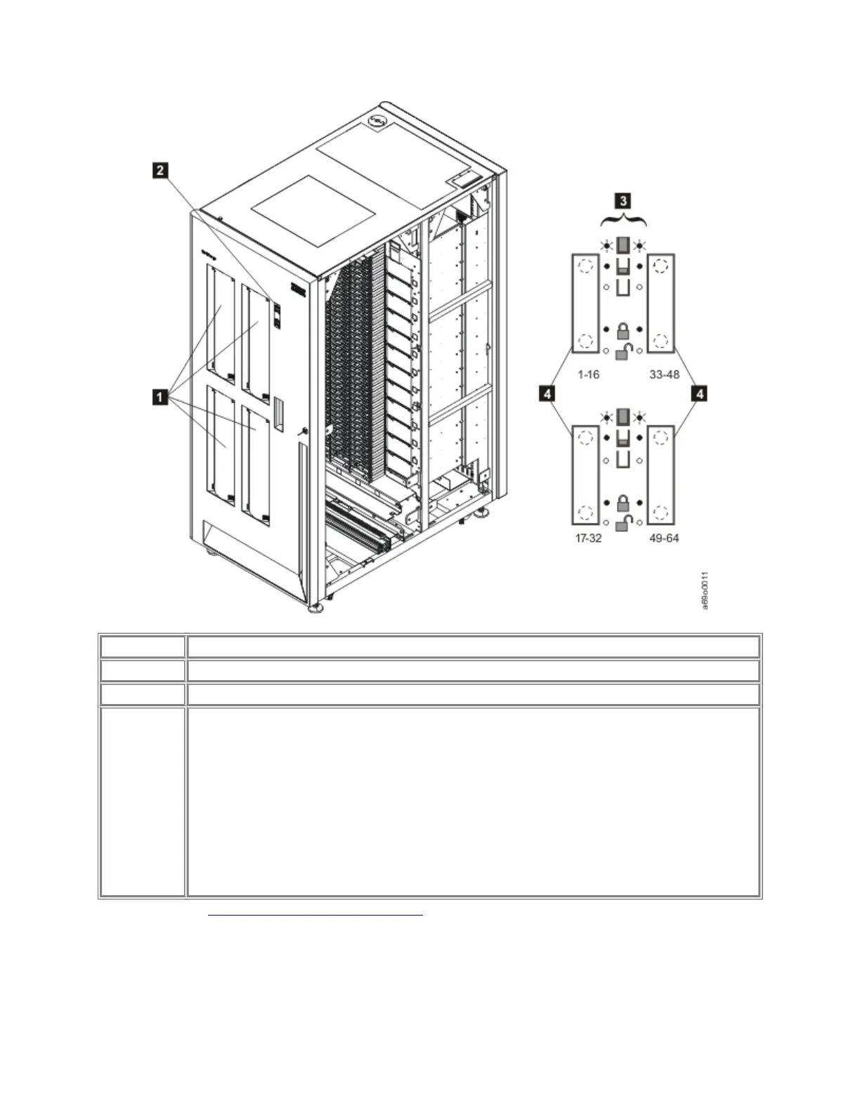
Table 1. Location of I/O slots and LED display in frames with four I/O stations
1 Indicates the location of the 4 1/O stations on a D23 frame.
2 Indicates the LED display.
3 Indicates the various on/off and locked/unlocked states of the LED display.
4 Indicates the 4 I/O stations, and below each I/O station, shows the rows
assigned to each station:
• Rows 1-16 are assigned to the upper left I/O station.
• Rows 17-32 are assigned to the lower left I/O station.
• Rows 33-48 are assigned to the upper right I/O station.
• Rows 49-64 are assigned to the lower right I/O station.
Parent topic: Overview of main components
Operator panel
 Loading...