33
INOVANCE TECHNOLGY EUROPE GmbH
SV660N Startup Procedure_EN_v1.4_20220826.docx
6.9 BLACKBOX
The black box is used for data collection when a fault occurs, which is convenient for analyzing the cause of the
fault.
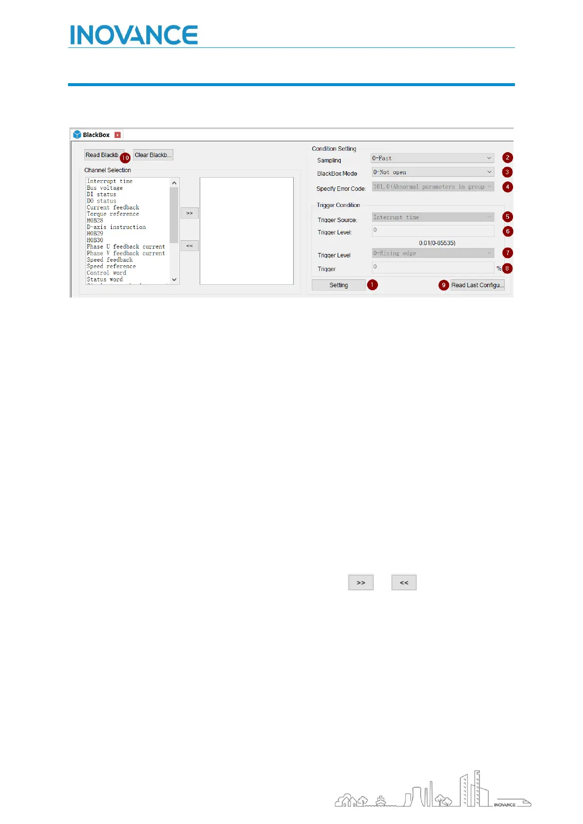
[01] Condition setting: enable the black box function, please set the condition parameters correctly, otherwise
the data will not be captured normally
[02] Sampling frequency: 0-fast (sampling frequency: 16 kHz, sampling interval 62.5us), 1-medium (4 kHz,
sampling interval 250us), 2-slow (1 kHz, sampling interval 1ms).
[03] Trigger mode: 0-not open, 1-arbitrary failure, 2-specified failure, 3-specified condition trigger; When the
trigger mode is 2-specified fault, you can select the corresponding specified fault code through the drop-down
menu [4]. At this time, you can also configure the trigger position. The trigger position refers to the data
collected before and after the trigger condition
When the trigger mode is 3-specified condition trigger, the trigger source selects the corresponding
observation channel variable through the drop-down menu [5], and sets the trigger level. When you want to
view the value of the observation variable crossing the trigger level [6] from small to large, the trigger level
selection [7] can select 0-rise Edge, if it crosses the trigger level from large to small, select 2-falling edge, etc.
Click the "Set" button [1] to send the black box trigger condition to the driver
In addition, users can click "Read last configuration" [9] to get the trigger condition information set last time; 3.
Black box data acquisition
Select the channels to be observed, up to 4 channels: click the button and to delete the channels
Click "Read Black Box Data" [10] to start reading the black box data. After reading, it will jump to the
oscilloscope interface to display the channel data

 Loading...


