Intel
®
Server Board S2600CP and Server System P4000CP TPS
Intel® Server Board S2600CP Connector/Header Locations and Pin-outs
Revision 1.1
Intel order number G26942-003
93
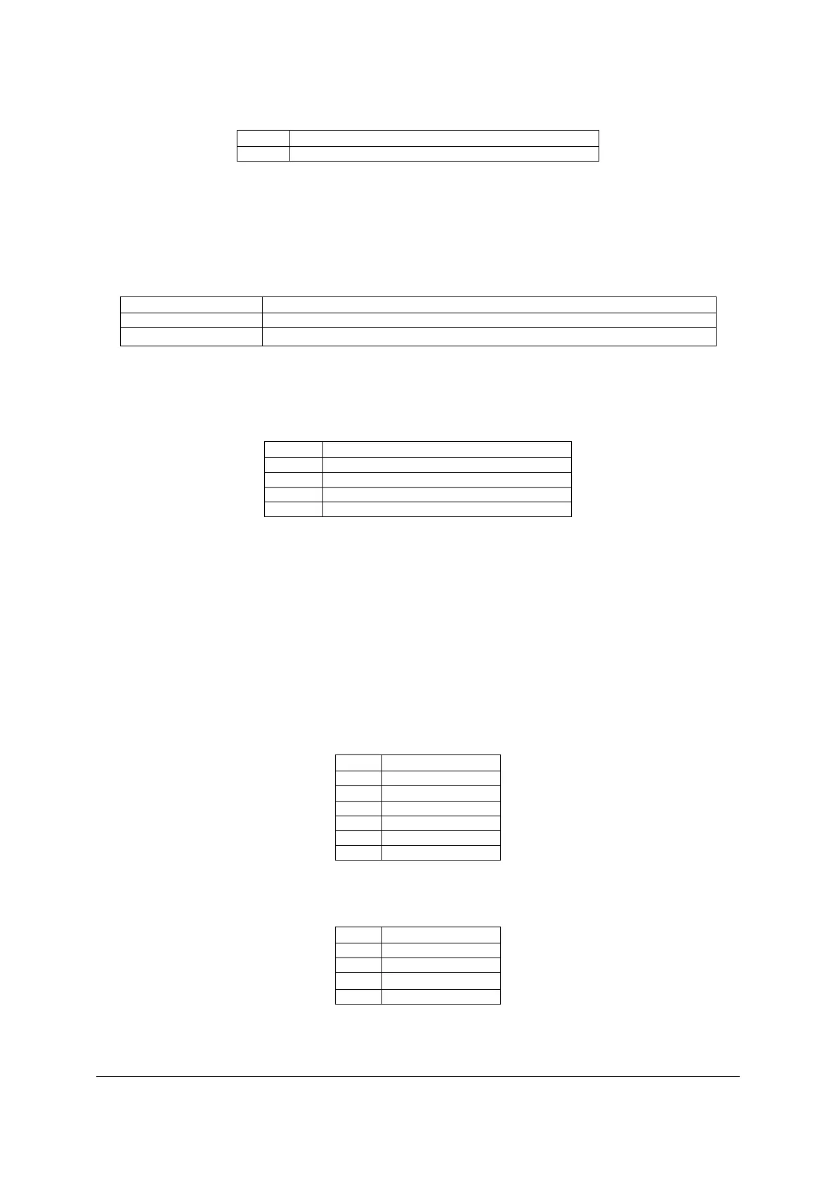
Pin Signal name
5 P3V3
7.4.5 Chassis Intrusion Header
The server board includes a 2-pin chassis intrusion header which can be used when the chassis
is configured with a chassis intrusion switch. The header has the following pin-out.
Table 46. Chassis Intrusion Header Pin-out
Header State Description
Pins 1 and 2 closed FM_INTRUDER_HDR_N is pulled HIGH. Chassis cover is closed.
Pins 1 and 2 open FM_INTRUDER_HDR_N is pulled LOW. Chassis cover is removed.
7.4.6 IPMB Connector
Table 47. IPMB Connector Pin-out
Pin Signal Name
1 SMB_IPMB_5VSTBY_DATA
2 GND
3 SMB_IPMB_5VSTBY_CLK
4 P5V_STBY
7.5 FAN Connectors
The server board provides support for nine fans. Seven of them are system cooling fans, two of
them are CPU fans.
7.5.1 System FAN Connectors
The six system cooling fan connectors near the front edge of the board are 6-Pin connectors;
the one system cooling fan near edge of the board is a 4-Pin connectors. Following table
provides the pin-out for all system fan connectors.
Table 48. 6-pin System FAN Connector Pin-out
Pin Signal Name
1 GND
2 12V
3 TACH
4 PWM
5 PRSNT
6 FAULT
Table 49. 4-pin System FAN Connector Pin-out
Pin Signal Name
1 GND
2 12V
3 TACH
4 PWM

 Loading...


