EasyManua.ls Logo

Intel S2600CP Family User Manual

Intel S2600CP Family
223 pages
To Next Page IconTo Next Page
To Previous Page IconTo Previous Page
Page #210 background imageLoading...
Page #210 background image
Appendix E: POST Code Diagnostic LED Decoder Intel
®
Server Board S2600CP and Server System P4000CP TPS
Revision 1.1
Intel order number G26942-003
194
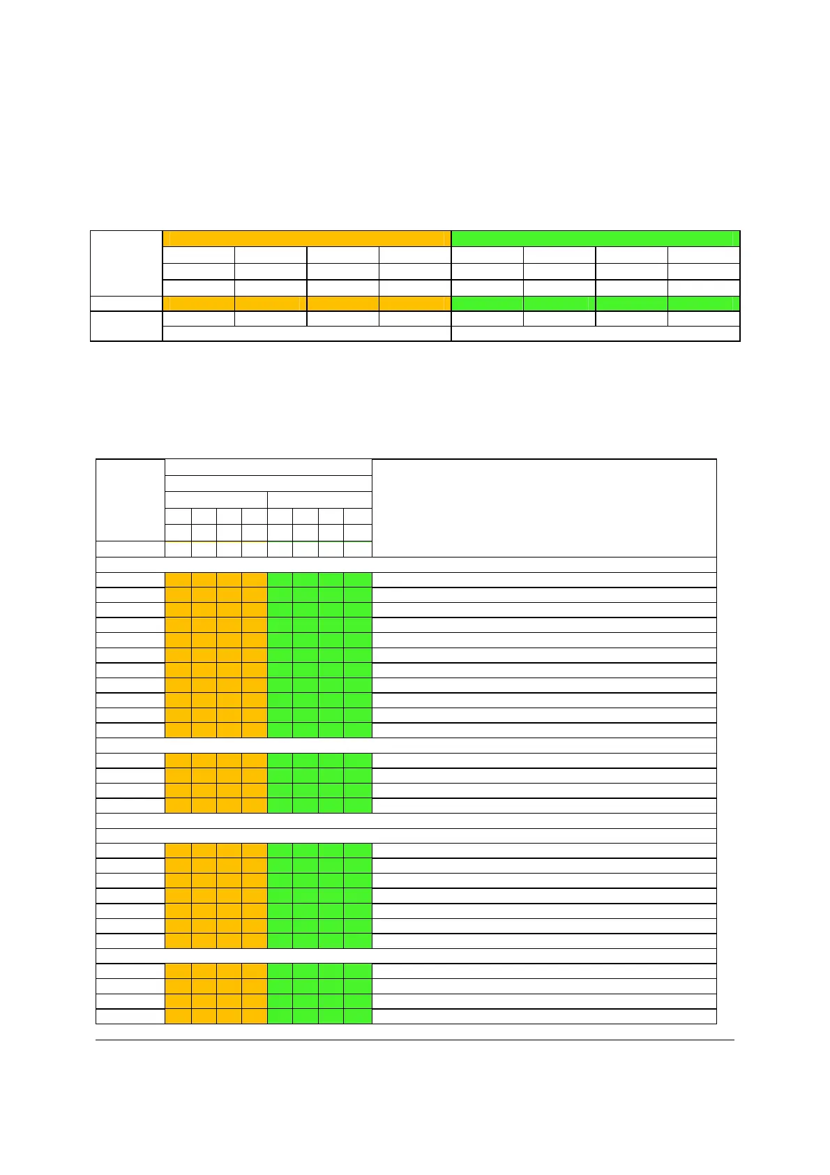
In the following example, the BIOS sends a value of ACh to the diagnostic LED decoder. The
LEDs are decoded as follows:
Table 151. POST Progress Code LED Example
LEDs
Upper Nibble AMBER LEDs Lower Nibble GREEN LEDs
MSB LSB
LED #7 LED #6 LED #5
LED #4
LED #3
LED #2
LED #1 LED #0
8h 4h 2h 1h 8h 4h 2h 1h
Status ON OFF ON OFF ON ON OFF OFF
Results
1 0 1 0 1 1 0 0
Ah Ch
Upper nibble bits = 1010b = Ah; Lower nibble bits = 1100b = Ch; the two are concatenated as
ACh
The following table provides a list of all POST progress codes.
Table 152. POST Progress Codes
Checkpoint Diagnostic LED Decoder Description
1 = LED On, 0 = LED Off
Upper Nibble
Lower Nibble
MSB LSB
8h 4h 2h 1h 8h 4h 2h 1h
LED # #7 #6 #5 #4 #3 #2 #1 #0
SEC Phase
01h 0 0 0 0 0 0 0 1 First POST code after CPU reset
02h 0 0 0 0 0 0 1 0 Microcode load begin
03h 0 0 0 0 0 0 1 1 CRAM initialization begin
04h 0 0 0 0 0 1 0 0 Pei Cache When Disabled
05h 0 0 0 0 0 1 0 1 SEC Core At Power On Begin.
06h 0 0 0 0 0 1 1 0 Early CPU initialization during Sec Phase.
07h 0 0 0 0 0 1 1 1 Early SB initialization during Sec Phase.
08h 0 0 0 0 1 0 0 0 Early NB initialization during Sec Phase.
09h 0 0 0 0 1 0 0 1 End Of Sec Phase.
0Eh 0 0 0 0 1 1 1 0 Microcode Not Found.
0Fh 0 0 0 0 1 1 1 1 Microcode Not Loaded.
PEI Phase
10h 0 0 0 1 0 0 0 0 PEI Core
11h 0 0 0 1 0 0 0 1 CPU PEIM
15h 0 0 0 1 0 1 0 1 NB PEIM
19h 0 0 0 1 1 0 0 1 SB PEIM
MRC Process Codes – MRC Progress Code Sequence is executed - See Table 63
PEI Phase continued…
31h 0 0 1 1 0 0 0 1 Memory Installed
32h 0 0 1 1 0 0 1 0 CPU PEIM (Cpu Init)
33h 0 0 1 1 0 0 1 1 CPU PEIM (Cache Init)
34h 0 0 1 1 0 1 0 0 CPU PEIM (BSP Select)
35h 0 0 1 1 0 1 0 1 CPU PEIM (AP Init)
36h 0 0 1 1 0 1 1 0 CPU PEIM (CPU SMM Init)
4Fh 0 1 0 0 1 1 1 1 Dxe IPL started
DXE Phase
60h 0 1 1 0 0 0 0 0 DXE Core started
61h 0 1 1 0 0 0 0 1 DXE NVRAM Init
62h 0 1 1 0 0 0 1 0 SB RUN Init
63h 0 1 1 0 0 0 1 1 Dxe CPU Init

Table of Contents

Question and Answer IconNeed help?

Do you have a question about the Intel S2600CP Family and is the answer not in the manual?

Intel S2600CP Family Specifications

General IconGeneral
CPU Socket TypeLGA 2011
Max CPU Count2
ChipsetIntel C602
Memory Slots16
Processor SupportIntel Xeon E5-2600/E5-2600 v2 series
Memory SupportDDR3
Network InterfaceGigabit Ethernet
Storage Controller6 x SATA 3Gb/s, 2 x SATA 6Gb/s
RAID SupportRAID 0, 1, 5, 10
Form FactorSSI EEB
USB Ports2 USB 3.0

Summary

Intel Server Board S2600CP Overview

Intel Server Board S2600CP Feature Set

Detailed list of features for the Intel Server Board S2600CP family.

Intel Server Board S2600CP Functional Architecture

Processor Support and Population Rules

Details on supported processors, socket assembly, and population rules for dual-processor configurations.

Processor Functions Overview

Overview of key processor features, supported technologies, and architecture details.

Intel C600 Chipset Functional Overview

Description of the key features and functions of the Intel C600 chipset.

System Security Features

BIOS Password Protection

Information on setting and managing BIOS administrator and user passwords.

Trusted Platform Module (TPM) Support

Details on the hardware-based security device for boot process integrity and data protection.

Platform Management Features

Server Management Function Architecture

Architecture and feature support for IPMI 2.0 and non-IPMI management.

Server Management Functional Specifications

Specifications for BMC internal clock, event logging, beep codes, and watchdog functionality.

Sensor Monitoring and Management

Details on BMC sensor monitoring, core sensors, and system health monitoring.

Connector and Header Locations

Power Connectors

Pin-out details for main power and CPU power connectors.

Jumper Blocks and BIOS Procedures

BIOS Default and Password Reset Procedures

Procedures for clearing CMOS and resetting BIOS passwords using jumpers.

Intel Server System P4000CP Front and Back Panel

Front Control Panel Overview

Overview of the front control panel features, buttons, and LEDs.

Intel Server System P4000CP Storage and Drive Bays

2.5-inch Hard Disk Drive Support

Details on 2.5-inch drive configurations, hot-swap backplanes, and enclosure management.

Intel Server System P4000CP Thermal Management

Thermal Operation and Configuration Requirements

Guidelines for maintaining optimal operating temperatures and system configuration.

Intel Server System P4000CP Power System Options

Power System Options Overview

Overview of power supply options for the P4000CP family systems.

550-W Power Supply Specifications

Detailed specifications for the 550-W non-redundant power supply.

750-W Power Supply Specifications

Detailed specifications for the 750-W redundant power supply.

Related product manuals