Intel
®
Server System P4000CP Storage and Peripheral Drive Bays
Intel
®
Server Board S2600CP and Server System P4000CP TPS
Revision 1.1
Intel order number G26942-003
114
Table 62. 3.5” Hard Disk Drive Activity LED States
Green
Condition Drive Type
Behavior
Power on with no drive activity
SAS LED stays on
SATA LED stays off
Power on with drive activity
SAS LED blinks off when processing a command
SATA LED blinks on when processing a command
Power on and drive spun down
SAS LED stays off
SATA LED stays off
Power on and drive spinning up
SAS LED blinks
SATA LED stays off
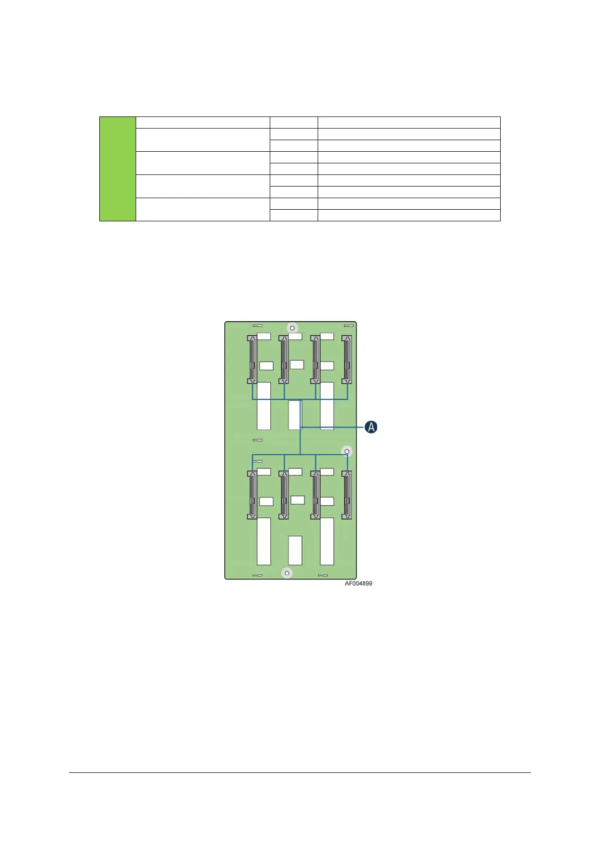
11.2.1 3.5” Drive Hot-Swap Backplane Overview
The backplane mount to the back of the drive bay assembly. On the front side the back plane
are mounted eight hard disk drive interface connectors (A), each providing both power and I/O
signals to the attached hard disk drives.
Figure 43. 3.5” Backplane, Front Side
On the backside of each backplane are several connectors. The following illustration identifies
each.

 Loading...


