Intel
®
Server Board S2600CP and Server System P4000CP TPS Intel
®
Server System P4000CP Power System Options
Revision 1.1
Intel order number G26942-003
151
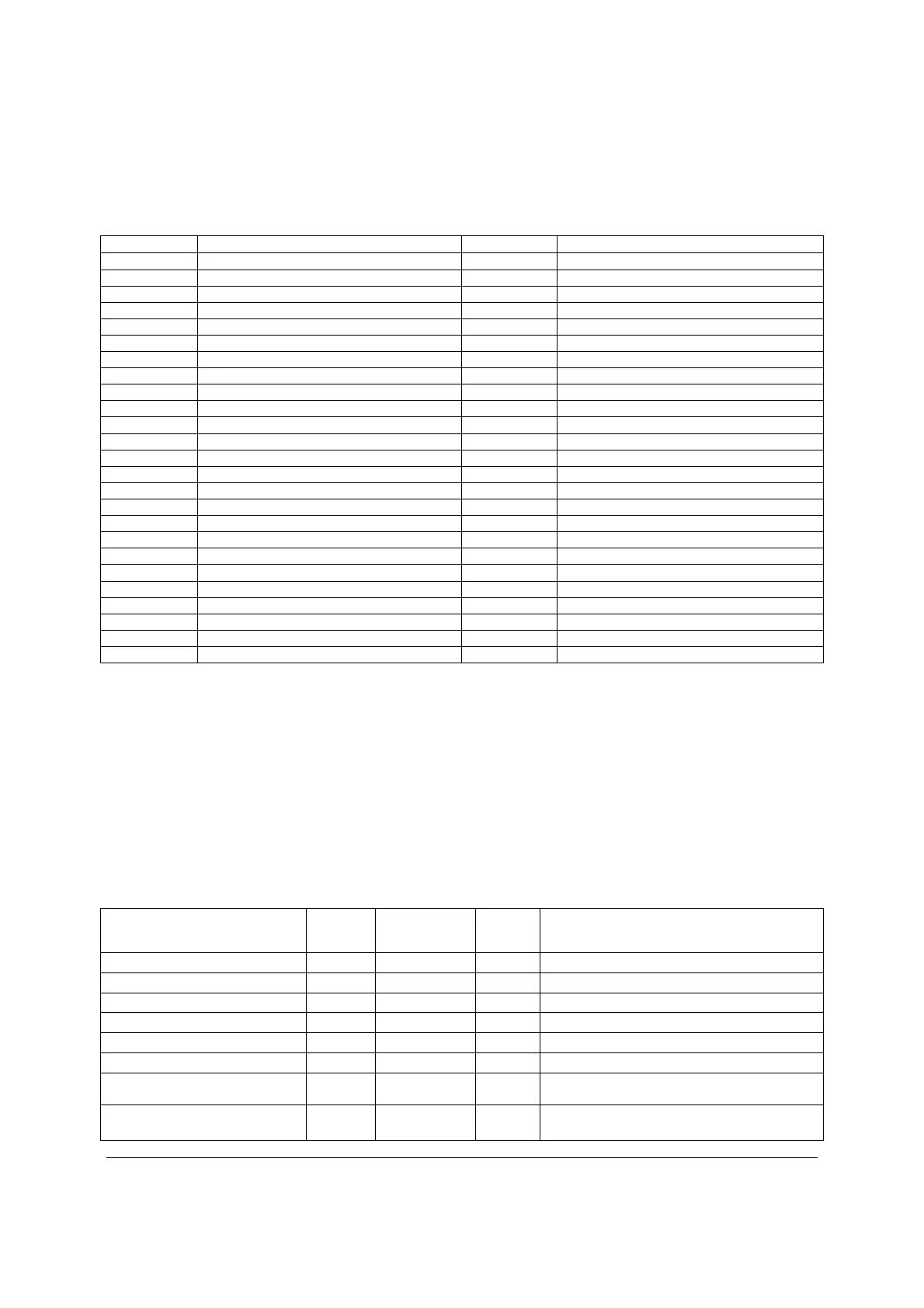
Table 109. Input Connector and Pin Assignment Diagrams
Pin Name Pin Name
A1 GND B1 GND
A2 GND B2 GND
A3 GND B3 GND
A4 GND B4 GND
A5 GND B5 GND
A6 GND B6 GND
A7 GND B7 GND
A8 GND B8 GND
A9 GND B9 GND
A10 +12V B10 +12V
A11 +12V B11 +12V
A12 +12V B12 +12V
A13 +12V B13 +12V
A14 +12V B14 +12V
A15 +12V B15 +12V
A16 +12V B16 +12V
A17 +12V B17 +12V
A18 +12V B18 +12V
A19 PMBus SDA B19 A0 (SMBus address)
A20 PMBus SCL B20 A1 (SMBus address)
A21 PSON B21 12V stby
A22 SMBAlert# B22 Cold Redundancy Bus
A23 Return Sense B23 12V load share
A24 +12V remote Sense B24 No Connect
A25 PWOK B25 Compatibility Pin
*The compatibility Pin is used for soft compatibility check. The two compatibility pins are
connected directly.
13.4.2.2 Output Wire Harness
The power distribution board has a wire harness output with the following connectors.
Listed or recognized component appliance wiring material (AVLV2), CN, rated min 85
C shall be
used for all output wiring.
Table 110. PDB Cable Length
From
Length,
mm To connector #
No of
pins Description
Power Supply cover exit hole 280 P1 24 Baseboard Power Connector
Power Supply cover exit hole 300 P2 8 Processor 0 connector
Power Supply cover exit hole 500 P3 8 Processor 1 connector
Power Supply cover exit hole 900 P4 5 Power FRU/PMBus connector
Power Supply cover exit hole 500 P5 5 SATA peripheral power connector for 5.25”
Extension from P5 100 P6 5 SATA peripheral power connector for 5.25”
Extension from P6 100 P7 4 Peripheral Power Connector for
5.25”/HSBP Power
Power Supply cover exit hole 600 P8 4 1x4 legacy HSBP Power Connector

 Loading...


