Intel
®
Server Board S2600CP and Server System P4000CP TPS Intel
®
Server System P4000CP Power System Options
Revision 1.1
Intel order number G26942-003
125
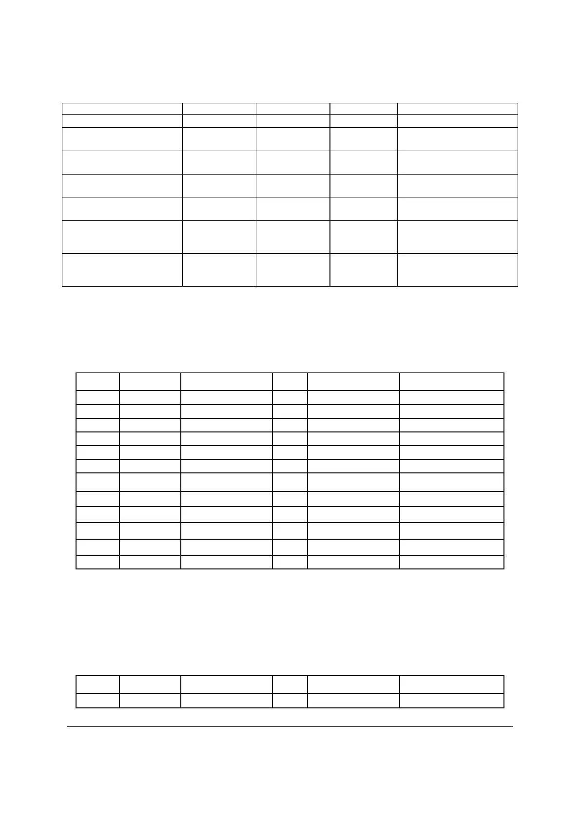
From Length (mm) To connector # No of pins Description
Connector for 5.25"
Extension from P4 100
P5
5
SATA Peripheral Power
Connector for 5.25"
Extension from P5 100
P6
4
Peripheral Power Connector
for 5.25"
Power Supply cover exit hole 600
P7
4
1x4 Legacy HSBP Power
Connector
Extension from P7 75
P8
4
1x4 Legacy HSBP Power
Connector
Power Supply cover exit hole 700 P9 4
1x4 Legacy HSBP
Power/Fixed HDD Adapter
Connection
Extension from P9 75 P10 4
1x4 Legacy HSBP
Power/Fixed HDD Adapter
Connection
13.2.1.1.1 Main power connector (P1)
Connector housing: 24- Pin Molex* Mini-Fit Jr 39-01-2245 (94V2) or equivalent
Contact: Molex* Minifit Jr, Crimp 5556 or equivalent
Table 64. P1 Main Power Connector
Pin Signal 18 awg color Pin Signal 18 awg color
1 +3.3 VDC Orange 13 +3.3 VDC Orange
2 +3.3 VDC Orange 14 -12 VDC Blue
3 COM Black 15 COM Black
4 +5 VDC* Red 16 PSON# Green
5 COM Black 17 COM Black
6 +5 VDC Red 18 COM Black
7 COM Black 19 COM Black
8 PWR OK Gray 20 Reserved N.C.
9 5VSB Purple 21 +5 VDC Red
10 +12V2 Yellow/Black 22 +5 VDC Red
11 +12V2 Yellow/Black 23 +5 VDC Red
12 +3.3 VDC Orange 24 COM Black
Note: 3.3V remote sense shall be double crimped into pin 13 if needed to meet regulation limits.
13.2.1.1.2 Processor/Memory Power Connector (P2)
Connector housing: 8- Pin Molex* 39-01-2085 (94V2) or equivalent
Contact: Molex*, Mini-Fit Jr, HCS, 44476-1111 or equivalent
Table 65. P2 Processor#1 Power Connector
Pin Signal 18 awg color Pin Signal 18 awg color
1 COM Black 5 +12V1 Yellow

 Loading...


