Intel
®
Server System P4000CP Power System Options Intel
®
Server Board S2600CP and Server System P4000CP TPS
Revision 1.1
Intel order number G26942-003
152
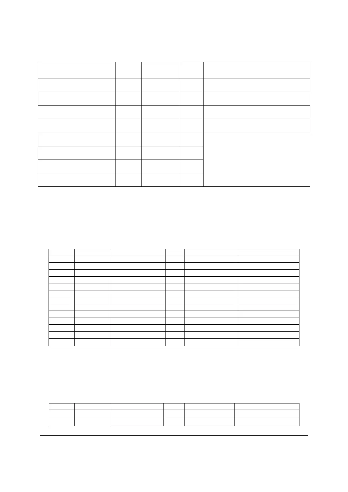
From
Length,
mm To connector #
No of
pins Description
Extension from P8 75 P9 4 1x4 legacy HSBP Power Connector
Power supply cover exit hole 700 P10 4 1x4 legacy HSBP Power/Fixed HDD
adaptor Connection
Extension from P10 75 P11 4 1x4 legacy HSBP Power/Fixed HDD
adaptor Connection
Connector only (no cable) N/a P12 4 Aux baseboard power connector for PCIe
slots
Connector only (no cable) N/a P13 4 GFX card aux connectors
Connector only (no cable) N/a P14 4
Connector only (no cable) N/a P15 4
Connector only (no cable) N/a P16 4
13.4.2.2.1 Baseboard power connector (P1)
Connector housing: 24-Pin Molex* Mini-Fit Jr. 39-01-2245 or equivalent
Contact: Molex* Mini-Fit, HCS Plus, Female, Crimp 44476 or equivalent
Table 111. P1 Baseboard Power Connector
Pin Signal 18 AWG Color Pin Signal 18 AWG Color
1 +3.3VDC
Orange 13 +3.3VDC Orange
3.3V RS Orange (24AWG)
2 +3.3VDC Orange 14 -12VDC Blue
3 COM Black 15 COM Black
4 +5VDC Red 16 PSON# Green (24AWG)
5 COM Black 17 COM Black
6 +5VDC Red 18 COM Black
7 COM Black 19 COM Black
8 PWR OK Gray (24AWG) 20 Reserved N.C.
9 5 VSB Purple 21 +5VDC Red
10 +12V1 Yellow 22 +5VDC Red
11 +12V1 Yellow 23 +5VDC Red
12 +3.3VDC Orange 24 COM Black
13.4.2.2.2 Processor#0 Power Connector (P2)
Connector housing: 8-Pin Molex* 39-01-2080 or equivalent
Contact: Molex* Mini-Fit, HCS Plus, Female, Crimp 44476 or equivalent
Table 112. P0 Processor Power Connector
Pin Signal 18 AWG color
Pin
Signal
18 AWG Color
1 COM Black 5* +12V1 White
2 COM Black 6 +12V1 White

 Loading...


