Appendix E: POST Code Diagnostic LED Decoder Intel
®
Server Board S2600CP and Server System P4000CP TPS
Revision 1.1
Intel order number G26942-003
196
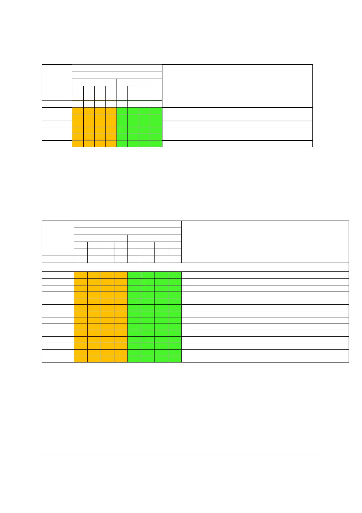
Checkpoint Diagnostic LED Decoder Description
1 = LED On, 0 = LED Off
Upper Nibble
Lower Nibble
MSB LSB
8h 4h 2h 1h 8h 4h 2h 1h
LED # #7 #6 #5 #4 #3 #2 #1 #0
F0h 1 1 1 1 0 0 0 0 PEIM which detected forced Recovery condition
F1h 1 1 1 1 0 0 0 1 PEIM which detected User Recovery condition
F2h 1 1 1 1 0 0 1 0 Recovery PEIM (Recovery started)
F3h 1 1 1 1 0 0 1 1 Recovery PEIM (Capsule found)
F4h 1 1 1 1 0 1 0 0 Recovery PEIM (Capsule loaded)
POST Memory Initialization MRC Diagnostic Codes
There are two types of POST Diagnostic Codes displayed by the MRC during memory
initialization; Progress Codes and Fatal Error Codes.
The MRC Progress Codes are displays to the Diagnostic LEDs that show the execution point in
the MRC operational path at each step.
Table 153. MRC Progress Codes
Checkpoint
Diagnostic LED Decoder
Description
1 = LED On, 0 = LED Off
Upper Nibble Lower Nibble
MSB
LSB
8h 4h 2h
1h 8h 4h
2h
1h
LED #7 #6 #5
#4 #3 #2
#1
#0
MRC Progress Codes
B0h
1 0 1 1 0 0 0 0
Detect DIMM population
B1h 1 0 1 1 0 0 0 1 Set DDR3 frequency
B2h 1 0 1 1 0 0 1 0 Gather remaining SPD data
B3h 1 0 1 1 0 0 1 1 Program registers on the memory controller level
B4h 1 0 1 1 0 1 0 0 Evaluate RAS modes and save rank information
B5h 1 0 1 1 0 1 0 1 Program registers on the channel level
B6h 1 0 1 1 0 1 1 0 Perform the JEDEC defined initialization sequence
B7h 1 0 1 1 0 1 1 1 Train DDR3 ranks
B8h 1 0 1 1 1 0 0 0 Initialize CLTT/OLTT
B9h 1 0 1 1 1 0 0 1 Hardware memory test and init
BAh 1 0 1 1 1 0 1 0 Execute software memory init
BBh 1 0 1 1 1 0 1 1 Program memory map and interleaving
BCh 1 0 1 1 1 1 0 0 Program RAS configuration
BFh 1 0 1 1 1 1 1 1 MRC is done
Memory Initialization at the beginning of POST includes multiple functions, including: discovery,
channel training, validation that the DIMM population is acceptable and functional, initialization
of the IMC and other hardware settings, and initialization of applicable RAS configurations.
When a major memory initialization error occurs and prevents the system from booting with data
integrity, a beep code is generated, the MRC will display a fatal error code on the diagnostic
LEDs, and a system halt command is executed. Fatal MRC error halts do NOT change the state
of the System Status LED, and they do NOT get logged as SEL events. The following table lists
all MRC fatal errors that are displayed to the Diagnostic LEDs.

 Loading...


