Intel
®
Server Board S2600CP and Server System P4000CP TPS
Intel
®
Server System P4000CP Storage and Peripheral Drive Bays
Revision 1.1
Intel order number G26942-003
111
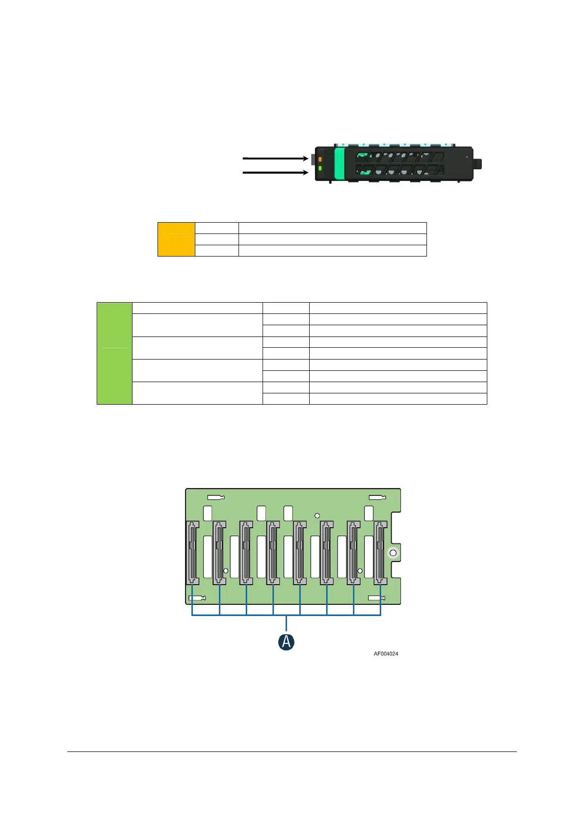
Light pipes integrated into the drive tray assembly direct light emitted from Amber drive status
and Green activity LEDs located next to each drive connector on the backplane, to the drive tray
faceplate, making them visible from the front of the system.
Table 59. 2.5” Hard Disk Drive Status LED States
Amber
Off No access and no fault
Solid On Hard Drive Fault has occurred
Blink RAID rebuild in progress (1 Hz), Identify (2 Hz)
Table 60. 2.5” Hard Disk Drive Activity LED States
Green
Condition Drive Type
Behavior
Power on with no drive activity
SAS LED stays on
SATA LED stays off
Power on with drive activity
SAS LED blinks off when processing a command
SATA LED blinks on when processing a command
Power on and drive spun down
SAS LED stays off
SATA LED stays off
Power on and drive spinning up
SAS LED blinks
SATA LED stays off
11.1.1 2.5” Drive Hot-Swap Backplane Overview
The 8x2.5” backplane is attached to the back of the 8x2.5” drive bay assembly. On the front side
of each backplane are mounted eight hard disk drive interface connectors (A), each providing
both power and I/O signals to attached hard disk drives.
Figure 40. 2.5” Backplane, Front Side
Amber Status LED
Green Activity LED

 Loading...


