Intel
®
Server System P4000CP Storage and Peripheral Drive Bays
Intel
®
Server Board S2600CP and Server System P4000CP TPS
Revision 1.1
Intel order number G26942-003
112
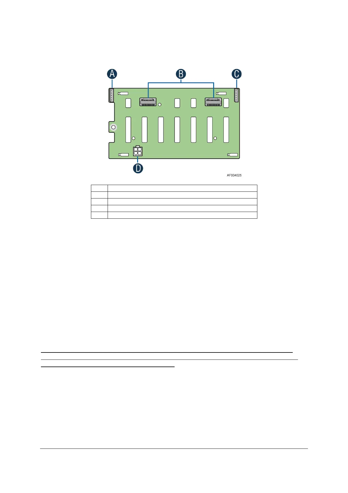
There are several connectors on the backside of each backplane. The following illustration
identifies each of them:
Label
Description
A I2C-Out cable connector for multi-backplane support
B 4-port Mini-SAS cable connectors
C I2C-In cable connector (From Server board or other backplane)
D Power connector
Figure 41. 2.5” Backplane, Back Side
A, C – I2C Cable Connectors – The backplane includes two cable connectors used as a
management interface between the server board and the installed backplanes. In systems
configured with multiple backplanes, a short jumper cable is attached between backplanes, with
connector B used on the first board and connector D used on the second board, extending the
manageability to each installed backplane.
B – Multi-port Mini-SAS Cable Connectors – The backplane includes two multi-port mini-SAS
cable connectors, each providing I/O signals for four SAS/SATA hard drives on the backplane.
Cables can be routed from matching connectors on the server board, add-in SAS/SATA RAID
cards, or optionally installed SAS expander cards.
D – Power Harness Connector – The backplane includes a 2x2 connector supplying power to
the backplane. Power is routed to each installed backplane by a multi-connector power cable
harness from the server board.
Note: The two SATA 6G connectors from ACHI (white connectors) on server board are not
recommended to connect to the 8X2.5 backplane. The LED indicators on the front side of the
8X2.5” drive bay will not light up if used as such.
11.1.2 Cypress* CY8C22545 Enclosure Management Controller
The backplanes support enclosure management using a Cypress* CY8C22545 Programmable
System-on-Chip (PSoC*) device.
The CY8C22545 drives the hard drive activity/fault LED, hard
drive present signal, and controls hard drive power-up during system power-on.

 Loading...


