Design and Environmental Specifications Intel
®
Server Board S2600CP and Server System P4000CP TPS
Revision 1.1
Intel order number G26942-003
166
electrical and/or thermal stress and for device maturity. You should view MTBF estimates as
“reference numbers” only.
Calculation Model: Telcordia* Issue 2, method I case 3
Operating Temperature: Server in 40° C ambient air
Operating Environment: Ground Benign, Controlled
Duty Cycle: 100%
Quality Level: II
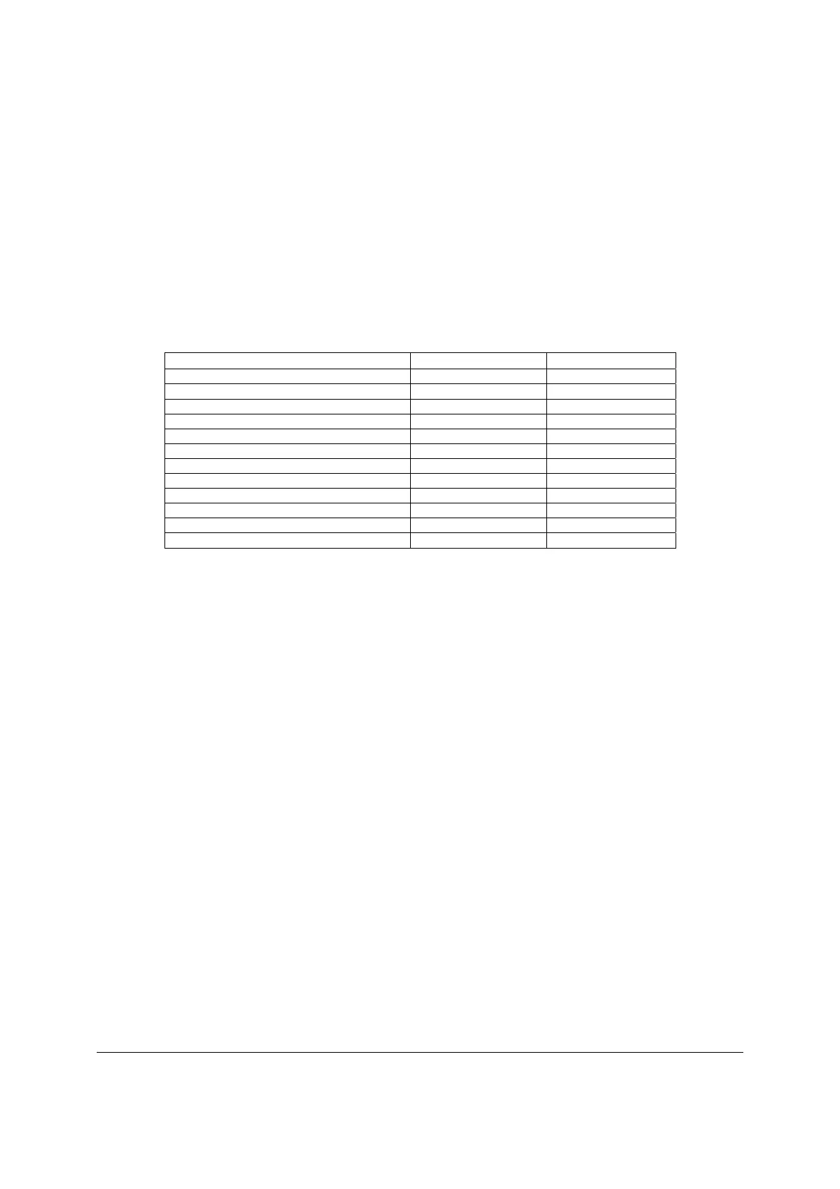
Table 140. MTBF Estimate
Assembly Failure Rate MTBF
Mother board 4,617.71 216,557
Integrated Circuits 1,756.55 569,298
Transistor_Bipolar 6.04 165,508,840
Transistor_MOSFET 418.11 2,391,663
Diodes 20.26 49,353,370
Diodes_LED 90.09 11,099,561
Resistors 960.02 1,041,635
Capacitors 213.71 4,679,143
E-Cap 571.98 1,748,312
Inductors 109.62 9,122,408
Connections 623.35 1,604,218
Misc 73.08 13,682,860
15.4 Server Board Power Distribution
This section provides power supply design guidelines for a system using the Intel
®
Server Board
S2600CP. The following diagram shows the power distribution implemented on these server
boards. For power supply data, please refer to the chapter that describe the power system
options including 550W or 750W power supply. Please note the intent of 550W/750W power
supply data is to provide customers with a guide to assist in defining and/or selecting a power
supply for custom server platform designs that utilize the server boards detailed in this
document.

 Loading...


