Intel® Server Board S2600CP Connector/Header Locations and Pin-outs
Intel
®
Server Board S2600CP and Server System P4000CP TPS
Revision 1.1
Intel order number G26942-003
94
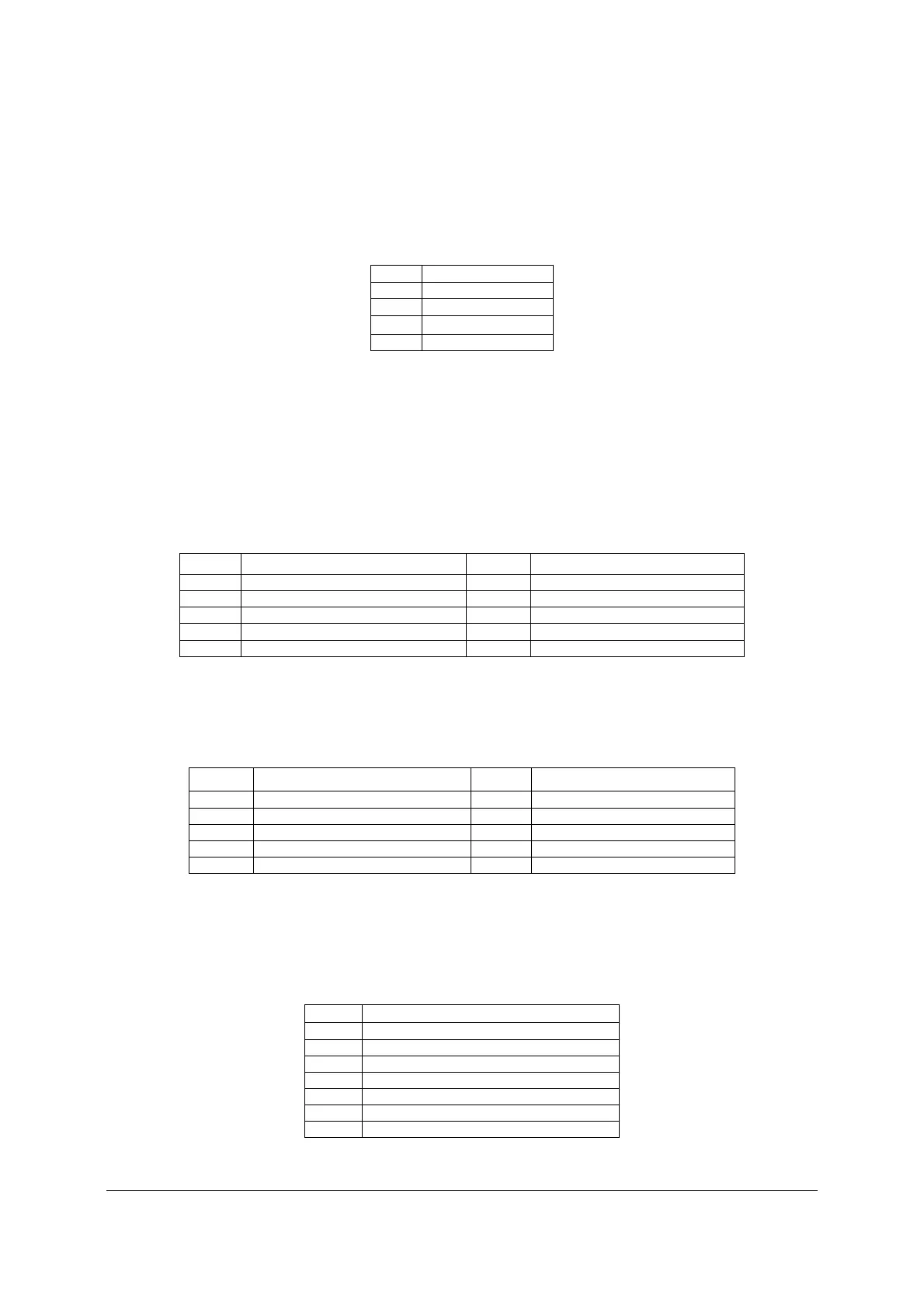
7.5.2 CPU FAN Connector
The two CPU fan connectors are 4-pin fan connectors. Following table provides the pin-out for
CPU fan connectors.
Table 50. CPU FAN Connector Pin-out
Pin Signal Name
1 GND
2 12V
3 TACH
4 PWM
7.6 Serial Port and Video Connectors
The server board includes two serial port connectors.
7.6.1 Serial Port A Connector (DB9)
Serial-A is an external RJ45 type connector and has the following pin-out configuration.
Table 51. Serial Port A Connector Pin-out
Pin Signal Name
Pin
Signal Name
1 SPA_DCD 2 SPA_SIN
3 SPA_SOUT_N 4 SPA_DTR
5 GND 6 SPA_DSR
7 SPA_RTS 8 SPA_CTS
9 SPA_RI
7.6.2 Serial Port B Connector
Serial-B is an internal 10-pin DH-10 connector and has the following pin-out.
Table 52. Serial Port B Connector Pin-out
Pin Signal Name Pin Signal Name
1 SPA_DCD 2 SPA_DSR
3 SPA_SIN 4 SPA_RTS
5 SPA_SOUT_N 6 SPA_CTS
7 SPA_DTR 8 SPA_RI
9 GND
7.6.3 Video Connector
The following table details the pin-out definition of the external VGA connector.
Table 53. Video Connector Pin-out details
Pin Signal Name
1 CRT_RED
2 CRT_GREEN
3 CRT_BLUE
4 N/C
5 GND
6 GND
7 GND

 Loading...


