Chapter 2: Installation
12 Advisor Advanced ATSx500A(-IP) Installation and Programming Manual
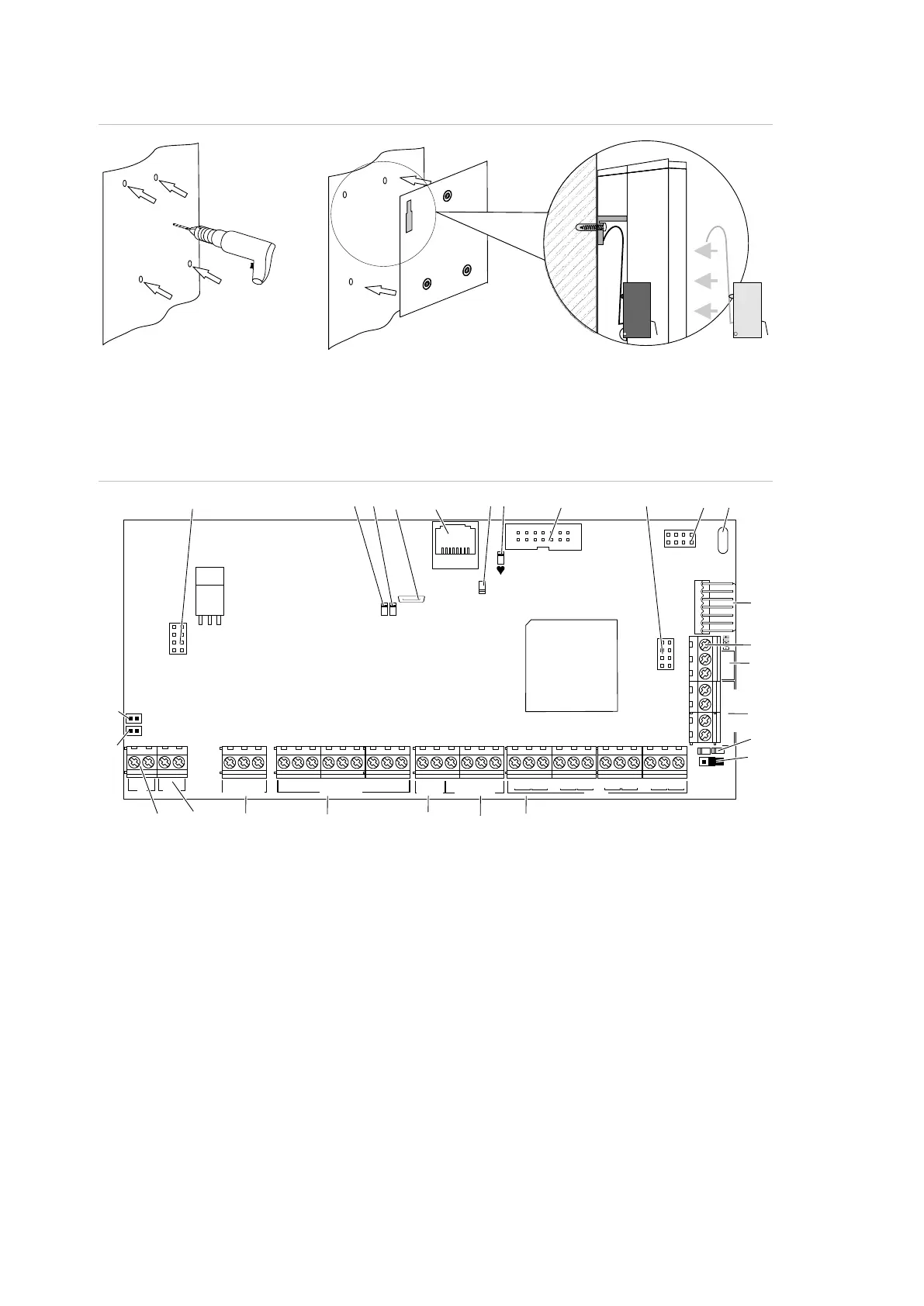
Figure 8: Large plastic housing (LP) pry-off tamper mount
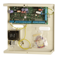
Advisor Advanced layout
Figure 9: Advisor Advanced ATSx500A(-IP) PCB layout
(1) Interface to output expander
(2) USB fault LED
(3) USB power LED
(4) USB connector (micro-A/B type)
(5) Ethernet RJ-45 connector (ATS-IP only)
(6) IP communication LED (ATS-IP only)
(7) Heartbeat LED
(8) MI-bus connector for MI devices
(9) Interface to input expander
(10) Interface to PSTN module
(11) Optional: enclosure ambient temperature
sensor
(12) ATS670 databus expander connector
(13) Panel earth terminal
(14) External tamper switch
(15) RS-485 system databus connections
(16) T2: Device firmware upgrade mode
(DFU)
(17) RS-485 system databus communication
LEDs
(18) T1: Restores installer default PIN
(19) System databus termination jumper
(20) AC power supply terminal
(21) Battery connection
(22) Low current (OC) outputs
(23) High current outputs
(24) Siren tamper switch
(25) 12 VDC auxiliary power output
(26) Zone inputs
()1 ()2 ()3 ()5 ()6 (10)(9)
(22)
(21)
(23)
(18)
(16)
(24) (25)
(19)
(17)
(15)
(14)
(26)
()4 (11)
(13)
RxTx
USB
MI
IP
CON12
CON13
T1
T2
S4
S5
+
+
S1
C
+
S2
C
T C
+
+
- -
1 C 2 3 C 4 5 C 6 7 C 8
~
~
+ -
AC
BATT
LC-OUTPUTS
HC-OUTPUTS
SIR TMP AUX POWER
INPUTS
CT
+
S3
C
CON16
NTC
COMMS
+12V 0VD+ D-
(12)
(20)
(8)
(7)
 Loading...