Chapter 2: Installation
24 Advisor Advanced ATSx500A(-IP) Installation and Programming Manual
(1) Zone terminal
C Common terminal
Z1 Zone 1 input
Z2 Zone 2 input
(2) Detector
A Alarm relay
T Tamper relay
Dual loop zone wiring
In dual loop wiring, one zone can detect a few detector states. At least two
resistors are used to define alarm and tamper states. Depending on the
programmed settings, there can be additional states defined as masking alarm or
sensor fault. These states can be the following:
• Short (tamper)
• Active (alarm)
• Normal
• Masking
• Sensor fault
• Open (tamper)
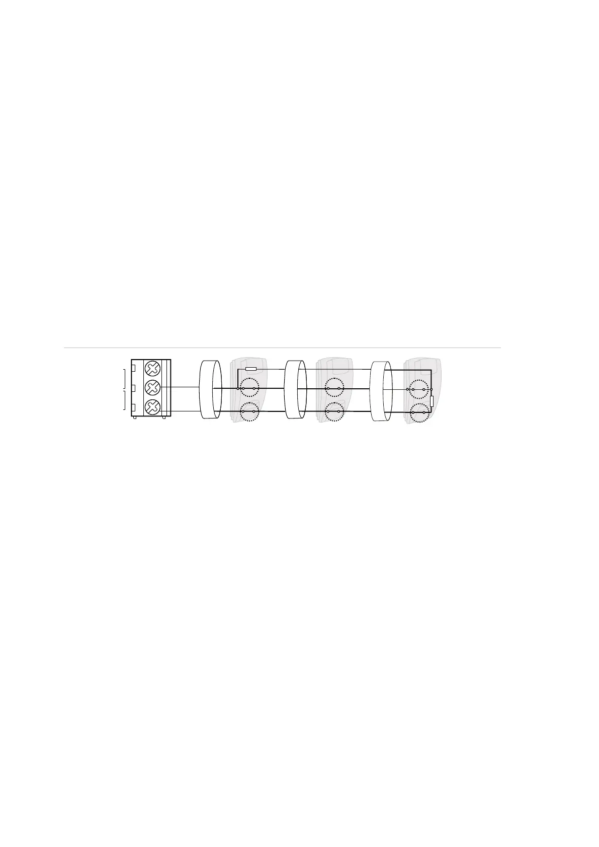
Figure 18: Dual loop example
(1) Zone terminal
C Common terminal
Z1 Zone 1 input
Z2 Zone 2 input
(2) Detector
A Alarm relay
T Tamper relay
Possible EOL connections are listed in “EOL connection types” on page 27.
Values for end-of-line resistors
The following list contains the values for end-of-line resistors and possible zone
states. Both the resistance and the voltage measured across the zone are
shown.
Depending on the input type and anti-masking option, the following EOL values
can be available.
C
Z2
(1)
RA
A
()2
RT
T
Z1
A A
T T
()2 ()2
 Loading...