Wiring
17
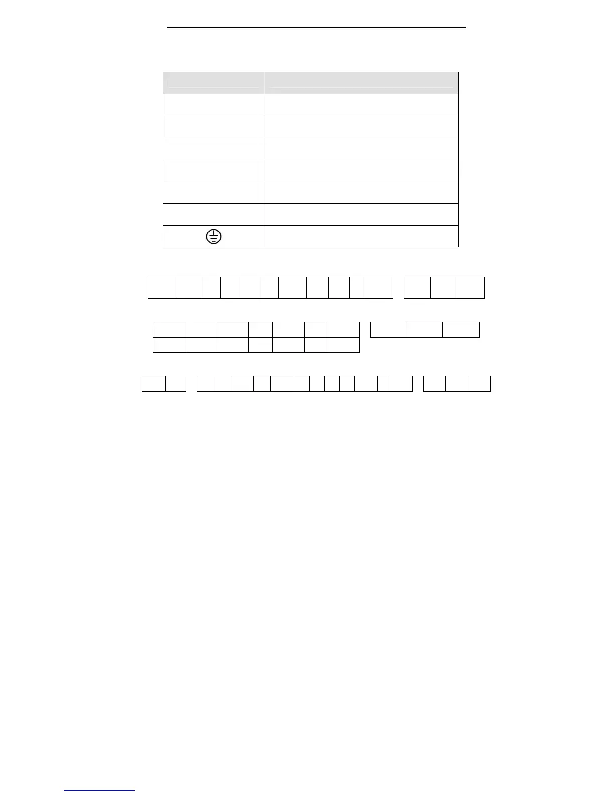
Main circuit terminal functions are summarized according to the terminal symbols in the
following table. Wire the terminal correctly for the desired purposes.
4.2.2 Control Circuit Terminals
485+ 485- S1 S2 S3 S4 COM AI2 AO Y +24V ROA ROB ROC
Figure 4.9 Control circuit terminals (0.4~0.75kW 1AC 220V).
485+ 485- +10V AO COM Y +24V ROA ROB ROC
AI1 GND AI2 S1 S2 S3 S4
Figure 4.10 Control circuit terminals (1.5~2.2kW).
485+ 485- AO AI1 GND AI2 +10V S1 S2 S3 S4 COM Y +24V ROA ROB ROC
Figure 4.11 Control terminals (4.0kW and above).
Terminal Symbol Function Description
R、S、T Terminals of 3 phase AC input
(+)、(-) Spare terminals of external braking unit
(+)、PB Spare terminals of external braking resistor
P1、(+) Spare terminals of external DC reactor
(-) Terminal of negative DC bus
U、V、W Terminals of 3 phase AC output
Terminal of ground
 Loading...
