Detailed Function Description
57
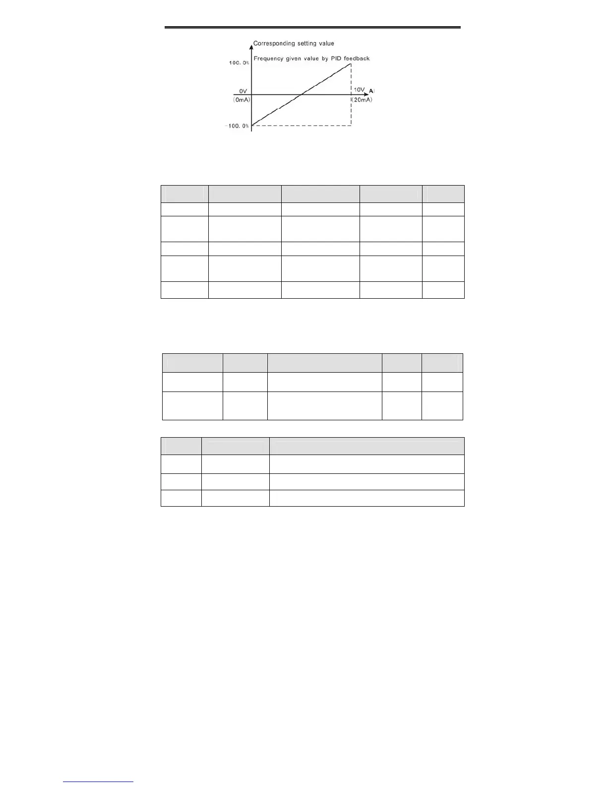
Figure 6.14 Relationship between AI and corresponding setting.
AI1 filter time constant is effective when there are sudden changes or noise in the analog
input signal. Responsiveness decreases as the setting increases.
Function
Code
Name Description Setting Range
Factory
Setting
P5.12 AI2 lower limit 0.00V~10.00V 0.00~10.00 0.00V
P5.13
AI2 lower limit
corresponding
setting
-100.0%~100.0% -100.0~100.0 0.0%
P5.14 AI2 upper limit 0.00V~10.00V 0.00~10.00 10.00V
P5.15
AI2 upper limit
corresponding
setting
-100.0%~100.0% -100.0~100.0 100.0%
P5.16
AI2 filter time
constant
0.00s~10.00s 0.00~10.00 0.10s
Please refer to description of AI1. When AI2 is set as 0~20mA current input, the
corresponding voltage range is 0~5V.
6.7 P6 Group--Output Terminals
Function Code Name Description
Setting
Range
Factory
Setting
P6.00
Y output
selection
Open-collector output 0~10 1
P6.01
Relay
output
selection
Relay output 0~10 3
OC/Relay output functions are indicated in the following table.
Setting
Value
Function Description
0 No output Output terminal has no function
1 Run forward ON: During forward run.
2 Run reverse ON: During reverse run.
 Loading...
