Detailed Function Description
49
Notice: Do not change these parameters, otherwise it may deteriorate the control
performance of inverter.
6.4 P3 Group—Vector Control
Function
Code
Name Description Setting Range
Factory
Setting
P3.00
ASR proportional
gain K
p
1
0~100 0~100 20
P3.01
ASR integral time
K
i
1
0.01~10.00s 0.01~10.00 0.50s
P3.02
ASR switching
point 1
0.00Hz~P3.05 0.00~P3.05 5.00Hz
P3.03
ASR proportional
gain K
p
2
0~100 0~100 25
P3.04
ASR integral time
K
i
2
0.01~10.00s 0.01~10.00 1.00s
P3.05
ASR switching
point 2
P3.02~P0.04 P3.02~P0.04 10.00Hz
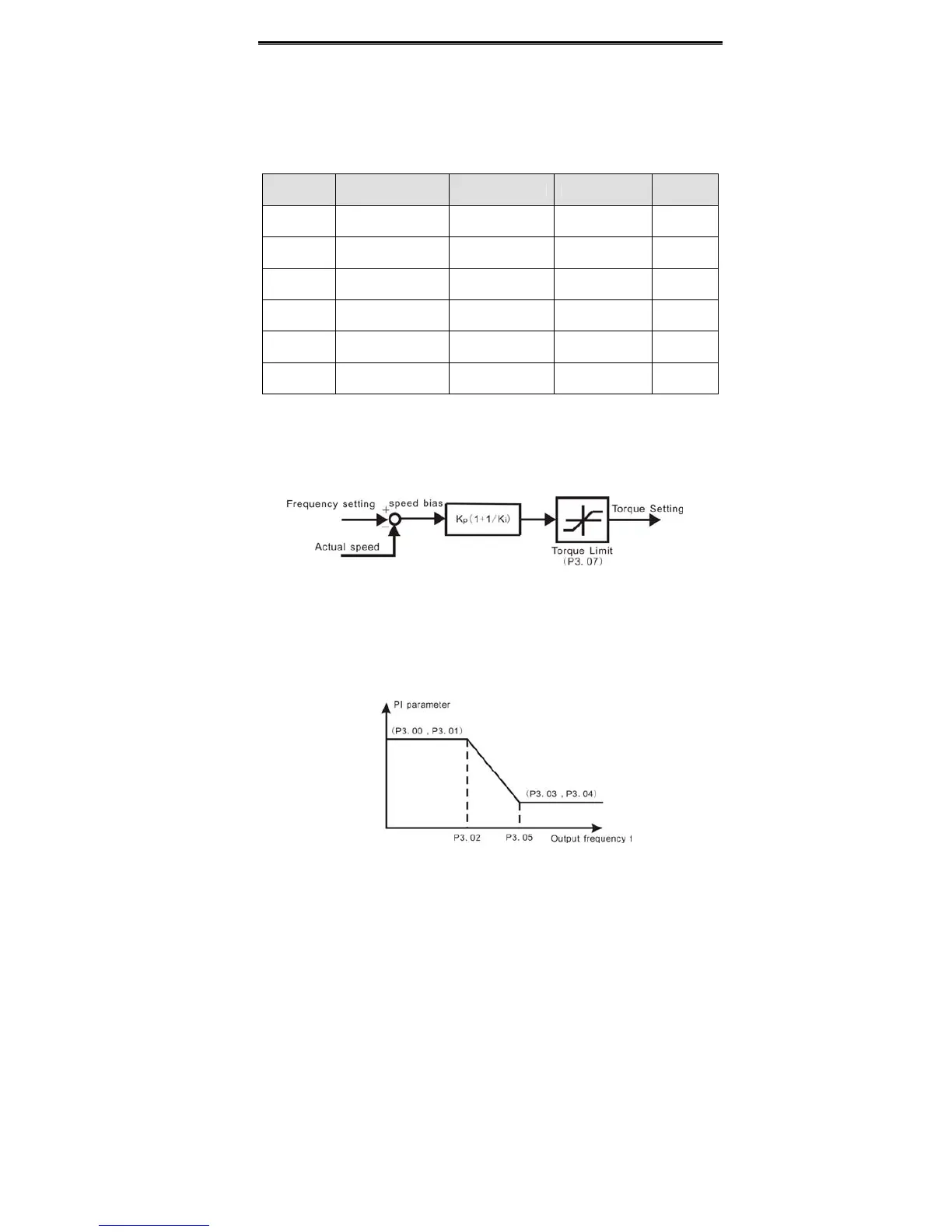
P3.00~P3.05 are only valid for vector control and torque control and invalid for V/F
control. Through P3.00~P3.05, user can set the proportional gain K
p
and integral time K
i
of speed regulator (ASR), so as to change the speed response characteristic. ASR's
structure is shown in following figure.
Figure 6.6 ASR diagram.
P3.00 and P3.01 only take effect when output frequency is less than P3.02. P3.03 and
P3.04 only take effect when output frequency is greater than P3.05. When output
frequency is between P3.02 and P3.05, K
p
and K
I
are proportional to the bias between
P3.02 and P3.05. For details, please refer to following figure.
 Loading...
