Detailed Function Description
68
This parameter is used to calibrate the bias between actual mechanical speed and
rotation speed. The formula is as below:
Actual mechanical speed = 120 * output frequency *P8.17 / Number of poles of motor
6.10 P9 Group--PID Control
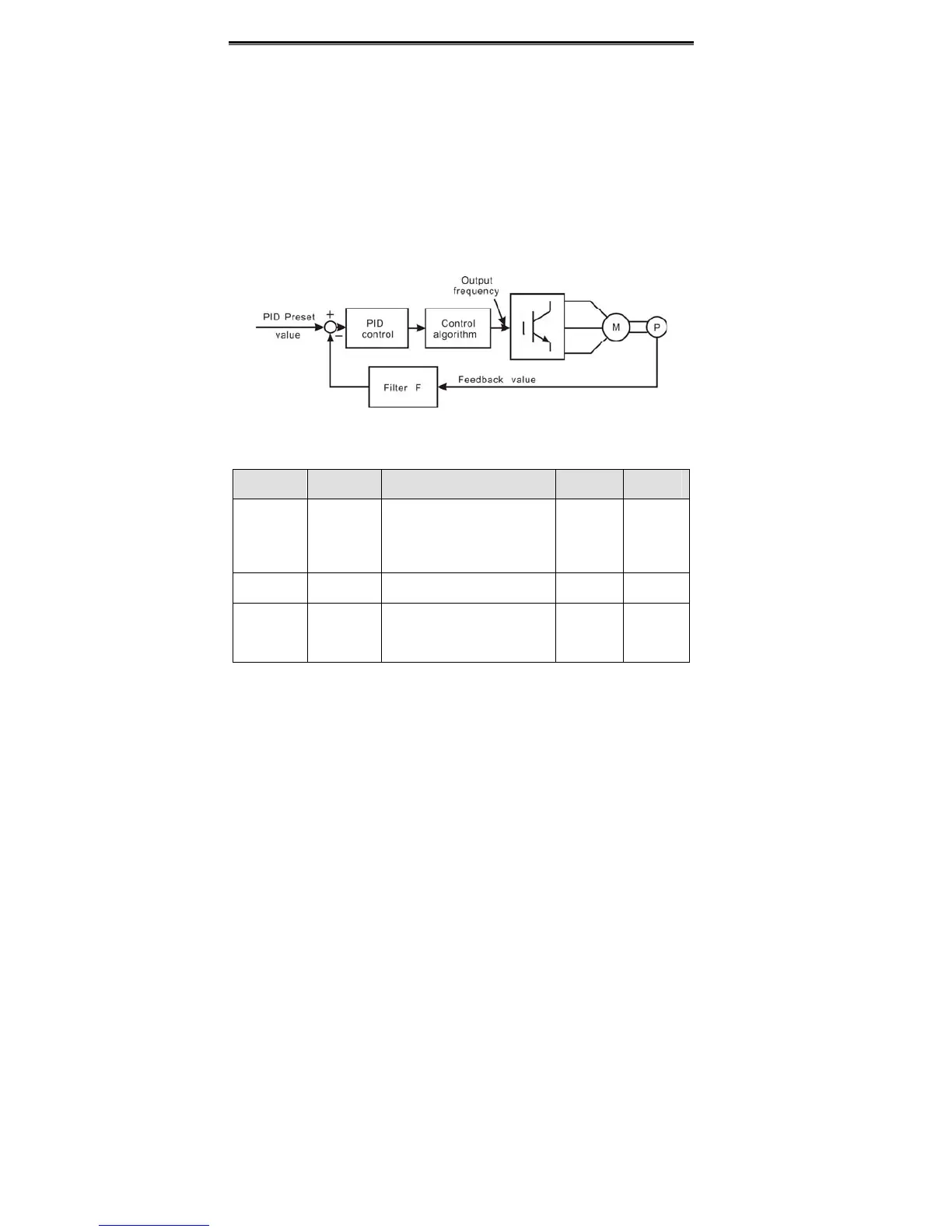
PID control is a common used method in process control, such as flow, pressure and
temperature control. The principle is firstly detect the bias between preset value and
feedback value, then calculate output frequency of inverter according to proportional gain,
integral and differential time. Please refer to following figure.
Figure 6.20 PID control diagram.
Function
Code
Name Description
Setting
Range
Factory
Setting
P9.00
PID preset
source
selection
0: Keypad
1: AI1
2: AI2
3: Communication
4: Multi-step
0~4 0
P9.01
Keypad
PID preset
0.0%~100.0% 0.0~100.0 0.0%
P9.02
PID
feedback
source
selection
0: AI1
1: AI2
2: AI1+AI2
3: Communication
0~3 0
These parameters are used to select PID preset and feedback source.
Notice:
Preset value and feedback value of PID are percentage value.
100% of preset value is corresponding to 100% of feedback value.
Preset source and feedback source must not be same, otherwise PID will be
malfunction.
 Loading...
