Detailed Function Description
56
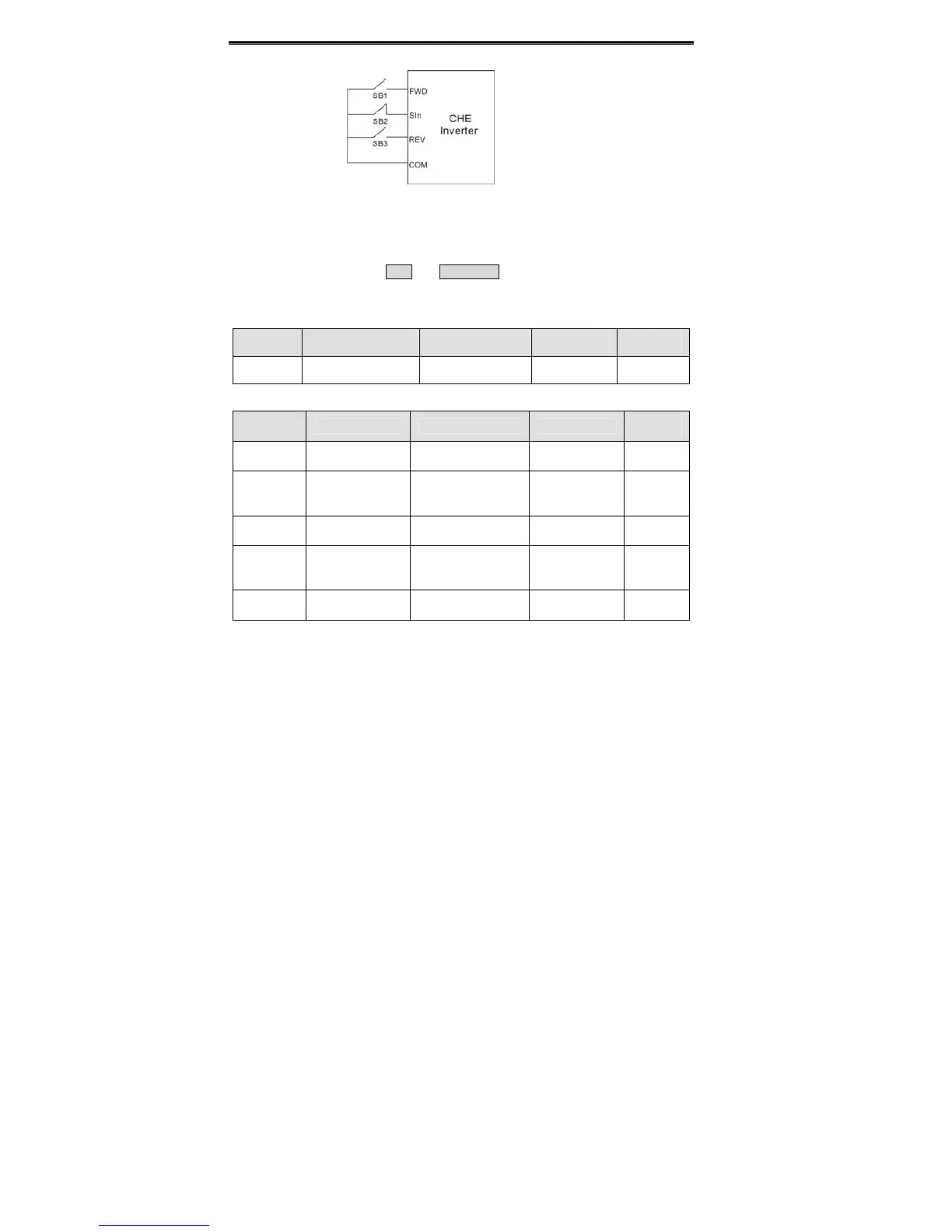
Figure 6.13 3-wire control mode2.
Notice: When 2-wire control mode is active, the inverter will not run in following
situation even if FWD/REV terminal is enabled:
z Coast to stop (press RUN and STOP/RST at the same time).
z Stop command from serial communication.
FWD/REV terminal is enabled before power on. Please refer to description of P1.11.
Function
Code
Name Description
Setting
Range
Factory
Setting
P5.06
UP/DOWN setting
change rate
0.01~50.00Hz/s 0.01~50.00 0.50Hz/s
Terminal UP/DOWN regulates the incremental rate of setting frequency.
Function
Code
Name Description Setting Range
Factory
Setting
P5.07 AI1 lower limit 0.00V~10.00V 0.00~10.00 0.00V
P5.08
AI1 lower limit
corresponding
setting
-100.0%~100.0% -100.0~100.0 0.0%
P5.09 AI1 upper limit 0.00V~10.00V 0.00~10.00 10.00V
P5.10
AI1 upper limit
corresponding
setting
-100.0%~100.0% -100.0~100.0 100.0%
P5.11
AI1 filter time
constant
0.00s~10.00s 0.00~10.00 0.10s
These parameters determine the relationship between analog input voltage and the
corresponding setting value. When the analog input voltage exceeds the range between
lower limit and upper limit, it will be regarded as the upper limit or lower limit.
The analog input AI1 can only provide voltage input, and the range is 0V~10V.
For different applications, the corresponding value of 100.0% analog setting is different.
For details, please refer to description of each application.
Notice: AI1 lower limit must be less or equal to AI1 upper limit.
 Loading...
