Detailed Function Description
71
P9.08 Bias limit 0.0~100.0% 0.0~100.0 0.0%
Sampling cycle T refers to the sampling cycle of feedback value. The PI regulator
calculates once in each sampling cycle. The bigger the sampling cycle, the slower the
response is.
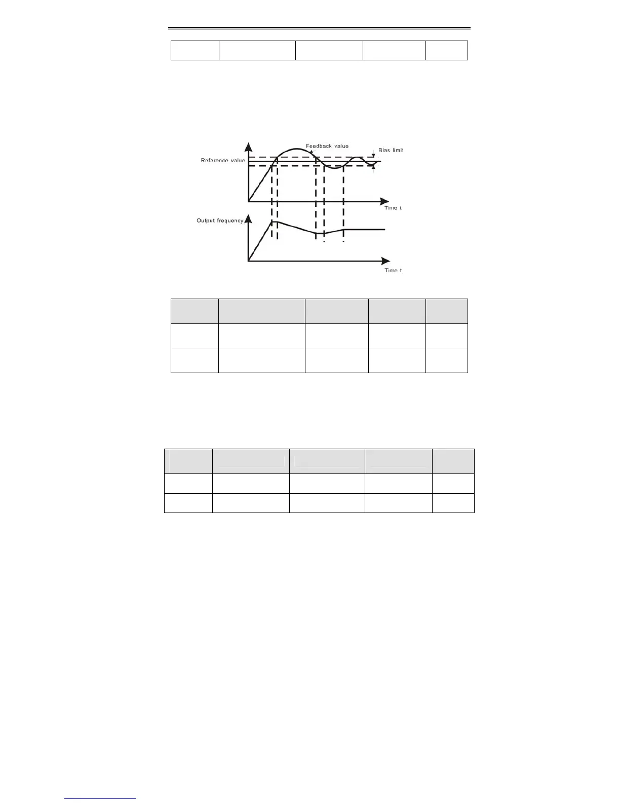
Bias limit defines the maximum bias between the feedback and the preset. PID stops
operation when the bias is within this range. Setting this parameter correctly is helpful to
improve the system output accuracy and stability.
Figure 6.25 Relationship between bias limit and output frequency.
Function
Code
Name Description
Setting
Range
Factory
Setting
P9.09
Feedback lost
detecting value
0.0~100.0% 0.0~100.0 0.0%
P9.10
Feedback lost
detecting time
0.0~3600.0s 0.0~3600.0 1.0s
When feedback value is less than P9.09 continuously for the period determined by P9.10,
the inverter will alarm feedback lost failure (PIDE).
Notice: 100% of P9.09 is the same as 100% of P9.01.
6.11 PA Group-- Multi-step Speed Control
Function
Code
Name Description Setting Range
Factory
Setting
PA.00 Multi-step speed 0 -100.0~100.0% -100.0~100.0 0.0%
PA.01 Multi-step speed 1 -100.0~100.0% -100.0~100.0 0.0%
 Loading...
