Wiring
28
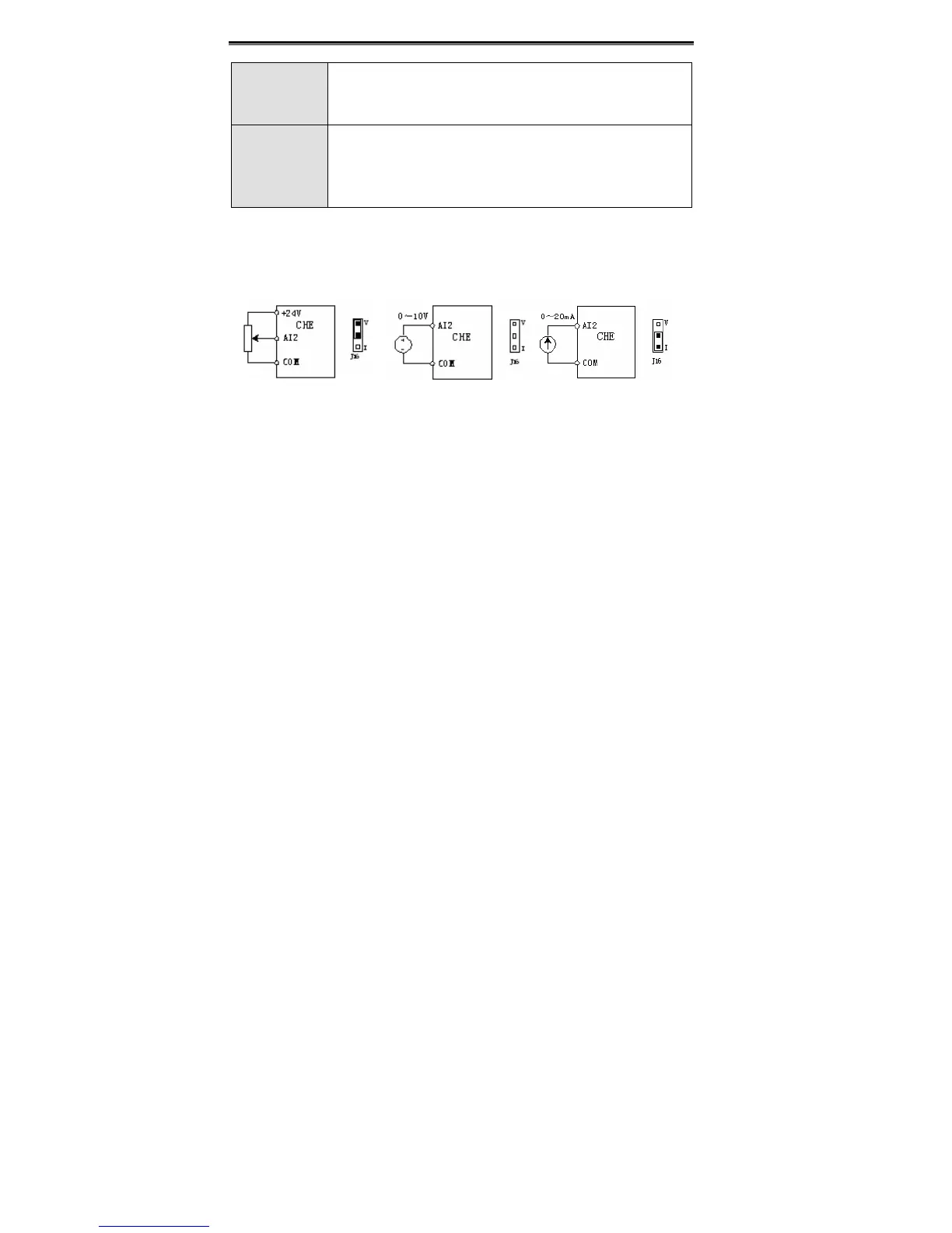
J16
Switch between (0~10V) voltage input and (0~20mA) current input.
V connect to GND means voltage input;
I connect to GND means current input.
J15
Switch between (0~10V) voltage output and (0~20mA) current
output.
V connect to OUT means voltage output;
I connect to OUT means current output.
4.6.4 Wiring description of size A (1AC 0.4~0.75kW)
AI2 can work in three modes (0~24V/0~10V/0~20mA) depend on the configuration of
J16.
0~24V input 0~10V input 0~20mA input
Figure 4.17 Wiring of size A (0.4~0.75kW 1AC).
To the external potentiometer, resistance should be greater than 3kΩ and power should
greater than 1/4W. Its resistance is recommended to be 5~10kΩ.
Notice:
The terminal will use the internal circuit to adjust the input signal. To the first two
work mode, the relative internal voltage range is 0~10V. And to the third work mode,
the relative internal voltage range is 0~5V.
4.7 Installation Guidline to EMC Compliance
4.7.1 General description of EMC
EMC is the abbreviation of electromagnetic compatibility, which means the device or
system has the ability to work normally in the electromagnetic environment and will not
generate any electromagnetic interference to other equipments.
EMC includes two subjects: electromagnetic interference and electromagnetic
anti-jamming.
According to the transmission mode, Electromagnetic interference can be divided into two
 Loading...
