Goodrive350-19 series VFD Product overview
- 18 -
Within the allowable input voltage range, the output current and power cannot exceed the rated
output current and power.
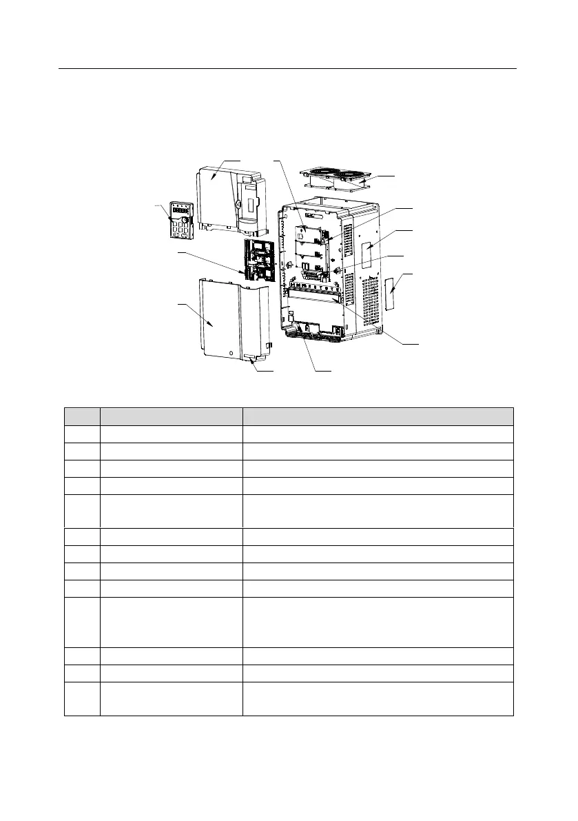
3.7 Structural diagram
The VFD structure is shown in the following figure (using the 380V 30kW VFD as an example):
Figure 3.7 Structural diagram
Used to protect internal components.
For details, see "Keypad".
Used to protect internal components.
Optional. For details, see "Extension cards".
Used to protect the control board and install extension
cards.
For details, see "Maintenance".
Used to connect the keypad.
For details, see "Product nameplate".
For details, see "Installing".
Optional. Using the ventilation hole cover can enhance
the protection rating but also increase the internal
temperature, which requires derating.
For details, see "Installing".
Indicator of the power supply.
GD350-19 product series
label
For details, see "Model designation code".
 Loading...


