Goodrive350-19 series VFD Installing
- 25 -
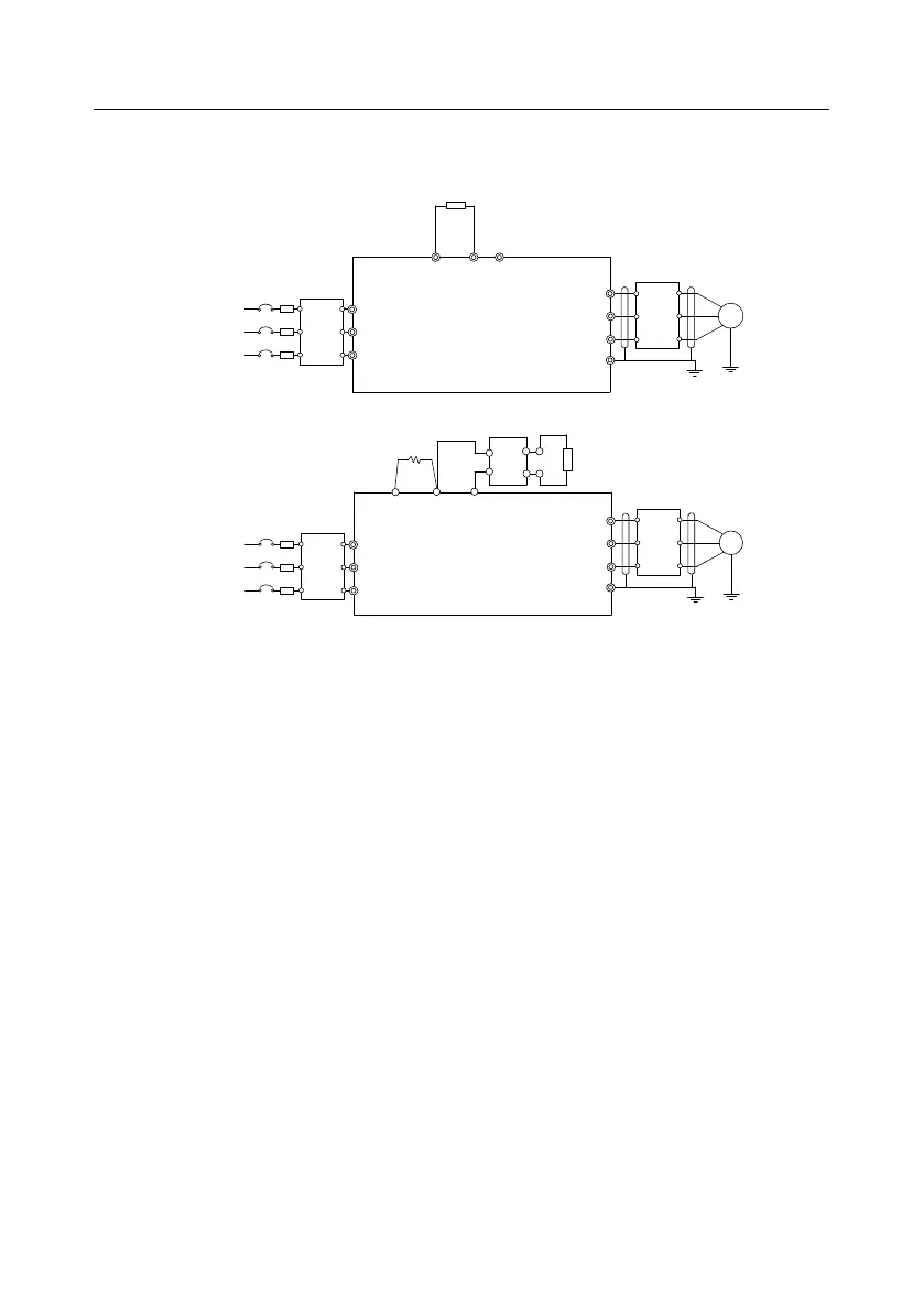
4.3 Main circuit standard wiring
4.3.1 Main circuit wiring diagram
VFD models of 132kW
and higher
Braking resistor
Braking unit
3PH power
380V±15%
50/60Hz
U
V
W
PE
P1
Fuse
R
S
T
M
(+) (-)
DC-
DC+
DC reactor
VFD models of 110kW
and lower
Braking resistor
Input
reactor
Input
filter
Fuse
3PH power
380V±15%
50/60Hz
R
S
T
U
V
W
PE
Output
reactor
Output
filter
M
(+) (-)
PB
Input
reactor
Input
filter
Output
reactor
Output
filter
Figure 4.7 Main circuit wiring diagram for the VFD models of AC 3PH 380V(-15%)–440V(+10%)
Note:
The fuse, DC reactor, braking unit, braking resistor, input reactor, input filter, output reactor and
output filter are optional parts. For details, see "Optional peripheral accessories".
P1 and (+) have been short connected by default for the 380V 132kW and higher VFD models. If
the VFD needs to connect to an external DC reactor, remove the short connector between P1
and (+).
When the braking resistor needs to be connected, remove the yellow warning labels marked with
PB, (+) and (-) from the terminal block before connecting the braking resistor wire. Otherwise,
poor contact may result.
 Loading...


