Goodrive350-19 series VFD Commissioning
- 43 -
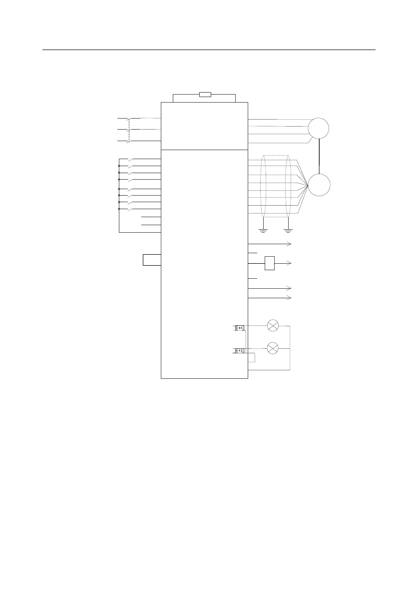
5.2 Commissioning lifting in closed-loop vector control
5.2.1 Wiring
(+) PB
GD350-19 VFD
R
S
T
R
S
T
M
3~
U
V
W
PG
PE
PWR
PGND
A1+
A1-
B1+
B1-
Z1+
Z1-
S1
S2
S3
S4
HDIA
HDIB
S5
S6
COM
Brake
output
VFD fault
output
Brake failure
output
Brake check
reminding/
overload
reminding
RO1A
RO1B
RO1C
RO2A
RO2B
RO2C
Y1
CME
HDO
COM
CME
+24V
Lifting
Lowering
Graded reference terminal 1
Graded reference terminal 2
Graded reference terminal 3
Graded reference terminal 4
Fault reset
Brake feedback
Braking resistor
S7
S8
PW
+24V
Figure 5.2 Wiring for lifting in closed-loop vector control
Note: If the wiring is performed according to Figure 5.2, most VFD parameters need no adjustment. If
the onsite function terminals are inconsistent with the terminals shown in the figure, adjust the input
and output terminal functions according to the actual wiring after selecting the closed-loop vector
controlled lifting application macro.
5.2.2 Commissioning procedure for hoisting-up closed-loop vector control
1. Check the wiring and ensure the wiring is proper.
2. Set P00.18=1.
3. Set motor nameplate parameters in P02.
4. Set P00.15=2. The keypad displays "-ΓUN-". Press the RUN key to perform static autotuning.
5. Set P90.00=1, set the encoder type parameter P20.00, set the pulse per resolution (PPR)
 Loading...


