Goodrive350-19 series VFD Extension cards
-455-
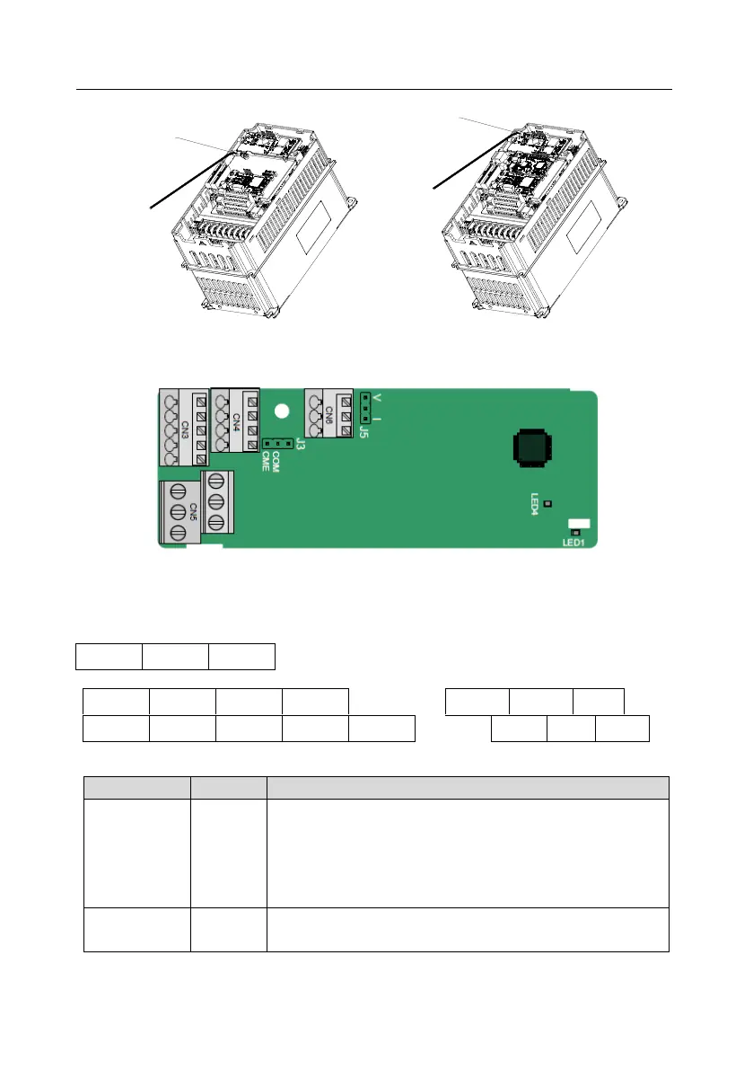
Grounding position of the
shielded cable
Grounding position of
the shielded cable
Figure A.4 Extension card grounding diagram
A.4 Function description of I/O extension card 1 (EC-IO501-00)
The terminals are arranged as follows:
CME and COM are short connected through J3 before delivery, and J5 is the jumper for selecting the
output type (voltage or current) of AO2.
Indicators are described as follows:
This indicator is on when the extension card is establishing a
connection with the control board; it blinks periodically after the
extension card is properly connected to the control board (the
period is 1s, on for 0.5s, and off for the other 0.5s); and it is off
when the extension card is disconnected from the control board.
This indicator is on after the I/O extension card is powered on by
the control board.
 Loading...


