Goodrive350-19 series VFD Technical data
-487-
rated power. When the altitude exceeds 1000m, derate by 1% for every increase of 100m. When the
altitude exceeds 3000m, consult the local INVT dealer or local INVT office for details.
B.2.2.3 Derating due to carrier frequency
The power of Goodrive350-19 series VFDs varies according to carrier frequencies. The VFD rated
power is defined based on the carrier frequency set in factory. If the carrier frequency exceeds the
factory setting, the power of the VFD is derated by 10% for each increased 1 kHz.
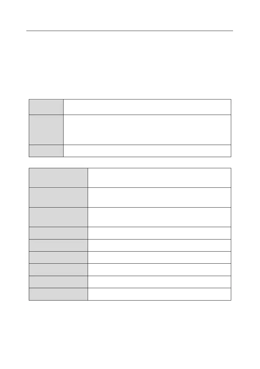
B.3 Grid specifications
AC 3PH 380V(-15%)–440V(+10%)
AC 3PH 520V(-15%)–690V(+10%)
According to the definition in IEC 60439-1, the maximum allowable short-circuit
current at the incoming end is 100 kA. Therefore, the VFD is applicable to
scenarios where the transmitted current in the circuit is no larger than 100 kA
when the VFD runs at the maximum rated voltage.
50/60 Hz ± 5%, with a maximum change rate of 20%/s
B.4 Motor connection data
Asynchronous induction motor or permanent magnetic
synchronous motor
0–U1 (rated voltage of the motor), 3PH symmetrical, Umax (rated
voltage of the VFD) at the field-weakening point
The short-circuit protection for the motor output meets the
requirements of IEC 61800-5-1.
1.5 times of the rated power of the motor
B.4.1 EMC compatibility and motor cable length
The following table describes the maximum motor cable lengths that meet the requirements of the EU
EMC directive (2004/108/EC) when the carrier frequency is 4 kHz.
 Loading...


