EasyManuals Logo
Home>INVT>DC Drives>Goodrive350-19 Series

INVT Goodrive350-19 Series User Manual

INVT Goodrive350-19 Series
540 pages
To Next Page IconTo Next Page
To Previous Page IconTo Previous Page
Page #474 background imageLoading...
Page #474 background image
Goodrive350-19 series VFD Extension cards
-467-
A.6 Function description of PG extension cards
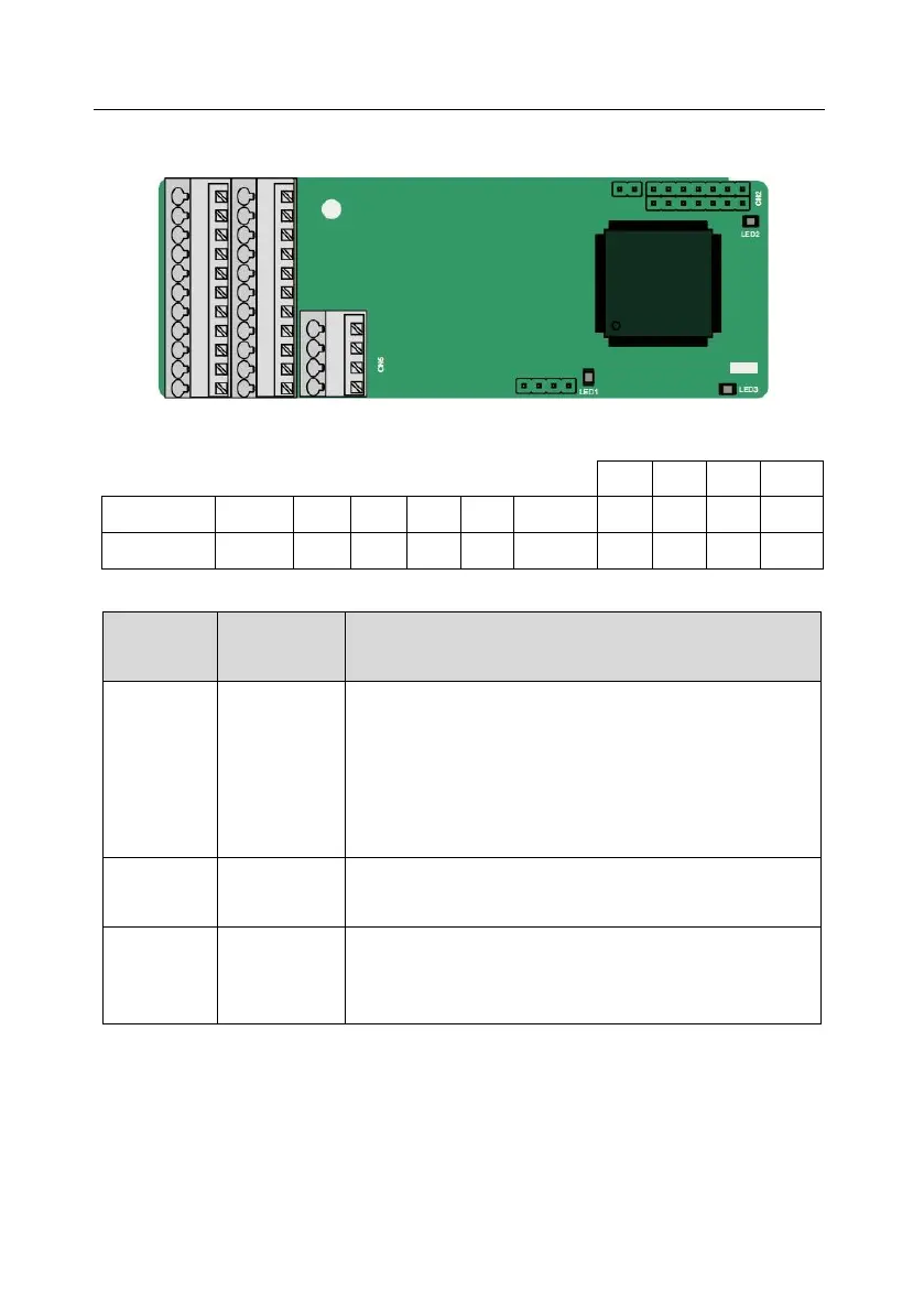
A.6.1 Sin/Cos PG card (EC-PG502)
The terminals are arrange as follows:
C1+
C1-
D1+
D1-
PE
AO+
BO+
ZO+
A1+
B1+
R1+
A2+
B2+
Z2+
PWR
GND
AO-
BO-
ZO-
A1-
B1-
R1-
A2-
B2-
Z2-
GND
The indicators are described as follows:
Indicator
No.
Name
Function
LED1
State
indicator
This indicator is on when the extension card is establishing a
connection with the control board; it blinks periodically after
the extension card is properly connected to the control board
(the period is 1s, on for 0.5s, and off for the other 0.5s); and it
is off when the extension card is disconnected from the control
board.
LED2
Power
indicator
This indicator is on after the control board feeds power to the
PG card.
LED3
Disconnection
indicator
This indicator is off when A1 and B1 of the encoder are
disconnected; it blinks when C1 and D1 of the encoder are
disconnected; and it is on the encoder signals are normal.

Table of Contents

Questions and Answers:

Question and Answer IconNeed help?

Do you have a question about the INVT Goodrive350-19 Series and is the answer not in the manual?

INVT Goodrive350-19 Series Specifications

General IconGeneral
BrandINVT
ModelGoodrive350-19 Series
CategoryDC Drives
LanguageEnglish

Related product manuals