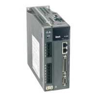
SV-DA200 series AC servo drives Faults and solutions
‐103‐
When P0.03 is 3 or 4, this parameter is used to set the exiting mode when the position mode can
be switched to other control modes.
Setting value Exiting mode
[0] Switch from position mode to other mode after positioning
1 Switch to other mode when the control mode switching command is invalid
P0.92
Data size 32bit Data format DEC
Modbus address 1184,1185 CANopen address 0x205C, 0x00
6.2 Autotuning control parameters (P1)
6.2.1 Inertia identification (Automatic gain)
P1.00
Inertia online
automatic estimation
Setting range Default Unit Available mode
0~1 0 % P S T F
This parameter is used to set whether to adjust the inertia ratio and adjust the gain automatically.
Setting value Meaning
[0] Invalid
1 Valid
P1.00
Data size 16bit Data format DEC
Modbus address 1200,1201 CANopen address 0x2100,0x00
P1.01 1
st
inertia ratio
Setting range Default Unit Available mode
0~10000 250 % P S T F
Rotation inertia ratio = Load inertia /motor rotation inertia x 100%,
If P1.01 is set correctly, the setting unit of P2.00 and P2.05 is Hz.
If P1.01 is larger than the actual value, the speed loop gain unit will increase, and if it is smaller
than the actual value, the speed loop gain unit will decrease.
If the online adjustment is valid, the real time inertia ratio will be updated to P1.01 and saved
into EEPROM every 30 minutes.
P1.01
Data size 16bit Data format DEC
Modbus address 1202,1203 CANopen address 0x2101,0x00
P1.02 2
nd
inertia ratio
Setting range Default Unit Available mode
0~10000 250 % P S T F
The definition is the same as P1.01.
Note: The automatic online gain adjustment is invalid for this parameter.
P1.02
Data size 16bit Data format DEC
Modbus address 1204,1205 CANopen address 0x2102,0x00
P1.03
Machine rigidity
setting
Setting range Default Unit Available mode
0~31 13 - P S T F
The bigger the value is the faster response and higher rigidity and easier vibration. In stable
system, higher rigidity setting makes fast response.

 Loading...