SV-DA200 series AC servo drives Commissoning
‐214‐
Refer to the adjustment steps of position mode in chapter 7.2.1.
7.3 Suppression of mechanical resonance
The mechanical system has a certain resonant frequency. If the response speed of the servo is
improved, the system may resonate (oscillation and abnormal noise) near the mechanical resonant
frequency. The resonance of the mechanical system can be effectively suppressed by setting the
parameters of the notch filters.
The notch filters achieve the goal of suppressing mechanical resonance by decreasing the gain of
certain frequency. We can set the frequency to be suppressed as well as the suppression extent with
relevant parameters.
This servo drive is equipped with four notch filters which can be set by 1
st
notch filter parameter
(P1.23, P1.24, P1.25), 2
nd
notch filter parameter (P1.26, P1.27, P1.28), 3
rd
notch filter parameter
(P1.29, P1.30, P1.31) and 4
th
notch filter parameter (P1.32, P1.33, P1.34). 1
st
and 2
nd
notch filter
parameters need to be set manually; 3
rd
and 4
th
notch filter parameters can be set by online
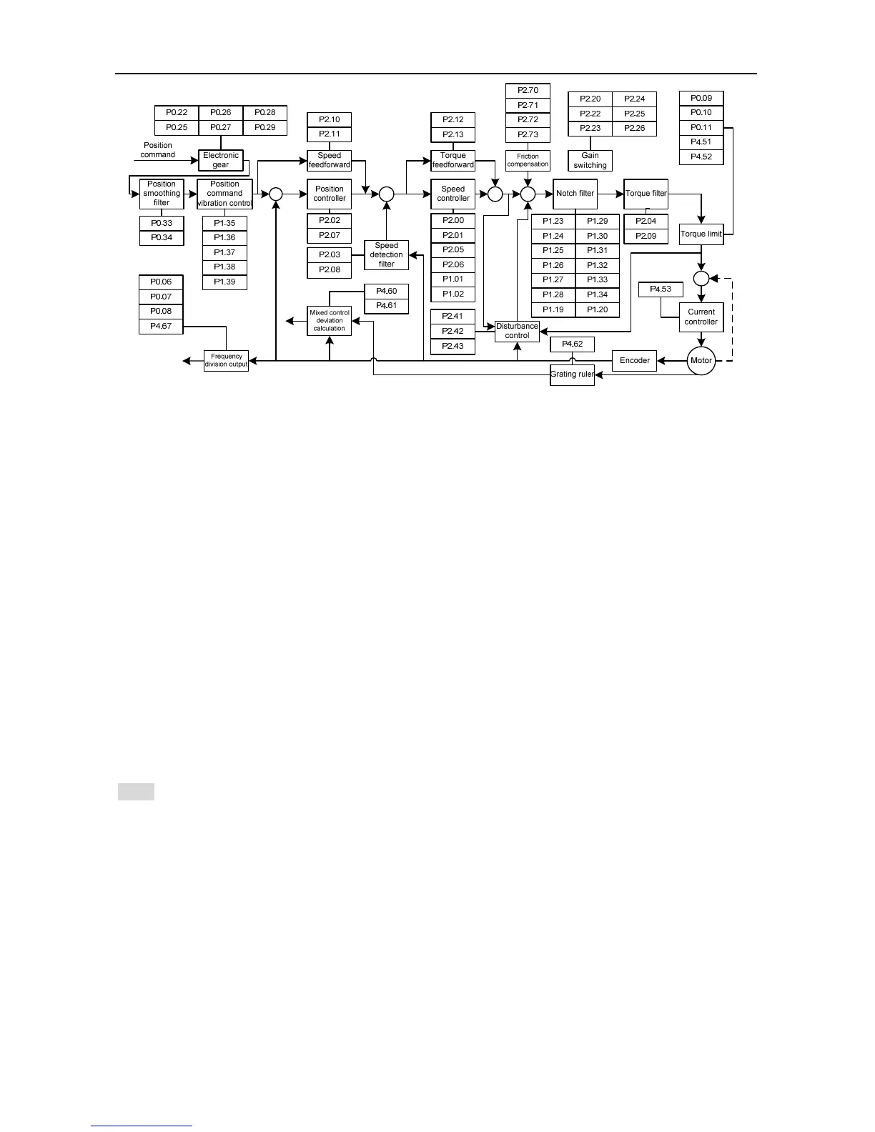
self-adaption. The position of notch filter in speed loop is shown in the figure in chapter 7.2.2. The
setup of notch filter is shown in the diagram below.
Note:
The notch filter is the lag factor for the servo system, so, if the center frequency of control width is
large, the vibration may be strengthened. It is recommended to increase the width unit it meets the
requirements.
The relationship between the Q value, width and depth is as below:
Q value of the notch filter=Center frequency of the notch wave /Width of the notch wave;
If the width of the notch is 0, the width of the filter is the deviation between two frequencies
when the power of the center frequency drops to -3dB;
The depth of the filter means the ratio of input and output, and its power spectrum strength

 Loading...