SV-DA200 series AC servo drives Control mode applications
‐42‐
4.4 CN1 function instruction
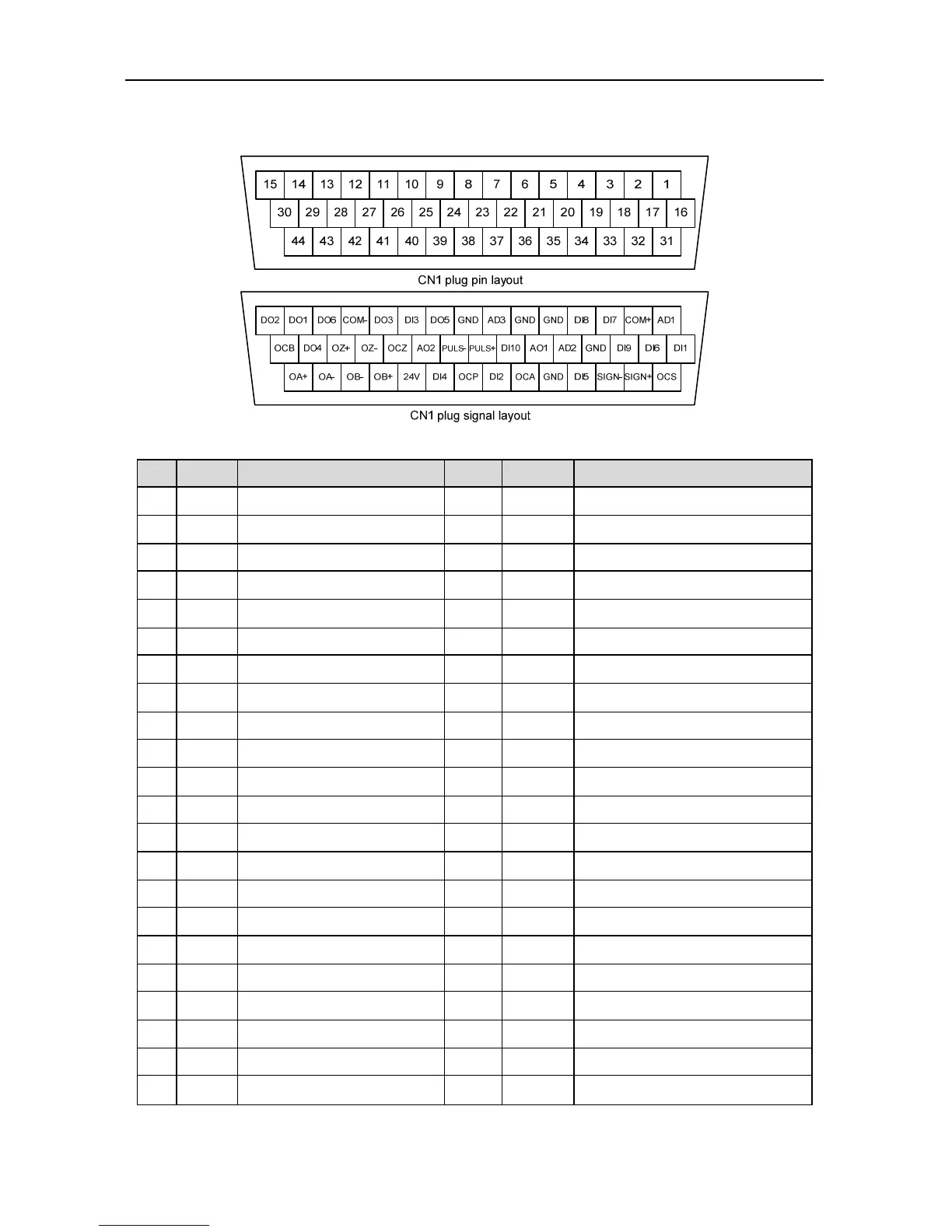
4.4.1 Pins of CN1 terminal
4.4.2 Definition of CN1 terminals
Pin Sign Function Pin Sign Function
1 AD1 Analog input 1 23 PULS+ Differential command pulse +
2 COM+ DI input common port 24 PULS- Differential command pulse -
3 DI7 Digital input 7 25 AO2 Analog output 2
4 DI8 Digital input 8 26 OCZ Open collector output of Z phase
5 GND Analog signal ground 27 OZ- Differential output - of Z phase
6 GND Analog signal ground 28 OZ+ Differential output + of Z phase
7 AD3 Analog input 3 29 DO4 Digital output 4
8 GND Analog signal ground 30 OCB Open collector output of B phase
9 DO5 Digital output 5 31 OCS Open collector command direction
10 DI3 Digital input 3 32 SIGN+ Differential command direction +
11 DO3 Digital output 3 33 SIGN- Differential command direction -
12 COM- DO output common ground 34 DI5 Digital input 5
13 DO6 Digital output 6 35 GND Analog signal ground
14 DO1 Digital output 1 36 OCA Open collector output of A phase
15 DO2 Digital output 2 37 DI2 Digital input 2
16 DI1 Digital input 1 38 OCP Open collector command pulse
17 DI6 Digital input 6 39 DI4 Digital input 4
18 DI9 Digital input 9 40 24V Internal 24V power supply
19 GND Analog signal ground 41 OB+ Differential output + of B phase
20 AD2 Analog input 2 42 OB- Differential output - of B phase
21 AO1 Analog output 1 43 OA- Differential output - of A phase
22 DI10 Digital input 10 44 OA+ Differential output + of A phase

 Loading...