SV-DA200 series AC servo drives Wiring instruction
‐35‐
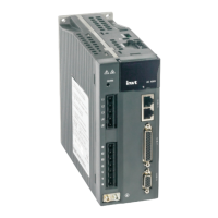
3.5.6 Rotary transformer encoder cable
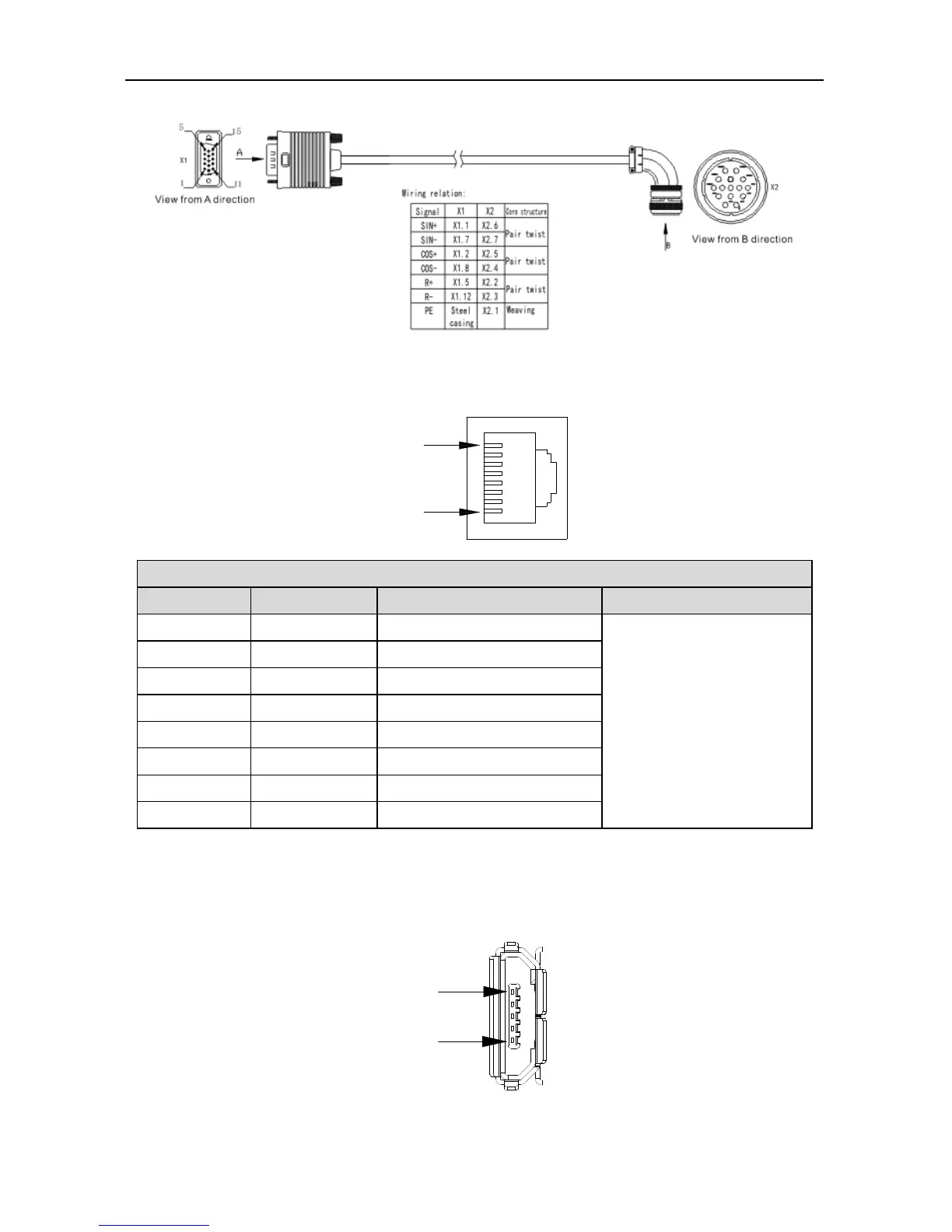
3.6 Wiring of 485/CAN-CN3 terminals
Pin8
Pin1
CN3 terminal function
Pin Name Function
Remark
1 GND_CAN CAN chip power GND
485 and CAN use the
same interface and each
signal has two pins for
multiple networking.
2 GND_485 485 chip power GND
3 - Unused
4 RS485+ RS485 data +
5 RS485- RS485 data -
6 - Unused
7 CAN_L CAN data -
8 CAN_H CAN data +
Note: EtherCAT bus-type drive, this port is standard network cable port definition, namely pin 1, 2, 3
and 6 correspond to Tx+, Tx-, Rx+ and Rx- respectively.
3.7 Wiring of USB-CN4 terminals
Pin5
Pin1

 Loading...