SV-DA200 series AC servo drives Control mode applications
‐39‐
Chapter 4 Control mode applications
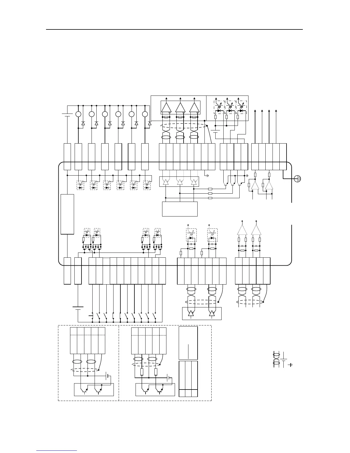
4.1 Standard wiring of the position mode
Frequency
divider
36 OCA
Output voltage range:
DC -10V~+10V;
Max output current:
3mA.
Position control mode
Analog torque limit of positive direction
(0V~+10V)
Analog torque limit of negative direction
(-10V~0V)
External
controller
Note: User-supplied power
DC12~24V
-+
EMG 39
SON 16
ZRS 37
POT 3
NOT 4
CLA 10
SC1 34
SC2 17
RPC 18
PLL 22
Command pulse
disabled
Retention pulse
clearing
Molecule 2 of electric
gear ratio
Molecule 1 of electric
gear ratio
Alarm clearing
Negative direction
drive disabled
Emergency stop
Servo enabling
Zero speed clamp
Positive direction
drive disabled
COM- 12
COM+ 2
24V 40
Internal DC24V power
Note: Capacity 100mA
12 COM-
15 ALM
14 RDY
29 ZSO
11 PLR
13 LM
9 BRK
44 OA+
43 OA-
41 OB+
42 OB-
FG
26 OCZ
30 OCB
AD2 20
GND 19
AD3 7
GND 8
FG
21 AO1
5 GND
25 AO2
6 GND
FG
Torque monitoring output
Speed monitoring output
AM26LS32
or equivalent chip
Note: User-supplied power
Vcc≤DC30V
-+
Fault
Servo ready
Speed zero
Positioning finished
Torque limiting
Brake release
Differential command
pulse input (max 4Mpps)
PULS+ 23
PULS- 24
OCP 38
2kΩ
SIGN+ 32
SIGN- 33
OCS 31
2kΩ
FG
PULS+ 23
PULS- 24
SIGN- 33
FG
SIGN+ 32
①24V power, built-in current limit resistor
②12~24V power, connect to external current
limit resistor
V
DC
12~24V
OCP 38
PULS- 24
SIGN- 33
FG
OCS 31
V
DC
24V
R R
V
DC
-1.5
R+68
≈10mA
Note: Max input of open collector is 200kpps
12V 1kΩ,1/4W
24V 2kΩ,1/3W
V
DC
R parameter
Ref
Max load capacity
of each output
terminal is
DC30V, 50mA
V
cc
≤DC30V;
OCA/B/Z
output current
≤50mA
28 OZ+
27 OZ-
……
High speed
optical coupler
35 GND
GND
-+
Vcc
5 GND
CN1
DI input
common port
DO output common
ground
Note: 1. ( ) is shielded twisted pair;
2. ( ) is power which is provided by the user;
3. ( ) is GND, pin numbers are 5/6/8/19/35.
DO output
common ground

 Loading...