Tecnical view
Engine speed/timing sensor on crankshaft
This is an inductive t ype sen sor and it is positioned on the engine flywheel (reference 8, Figure 1).
It generates signals obtained by means of the magnet ic flow lines that close u p through the holes that are made in the flywheel.
The electronic unit uses this signal in order to detect different engine r.p.m. states.
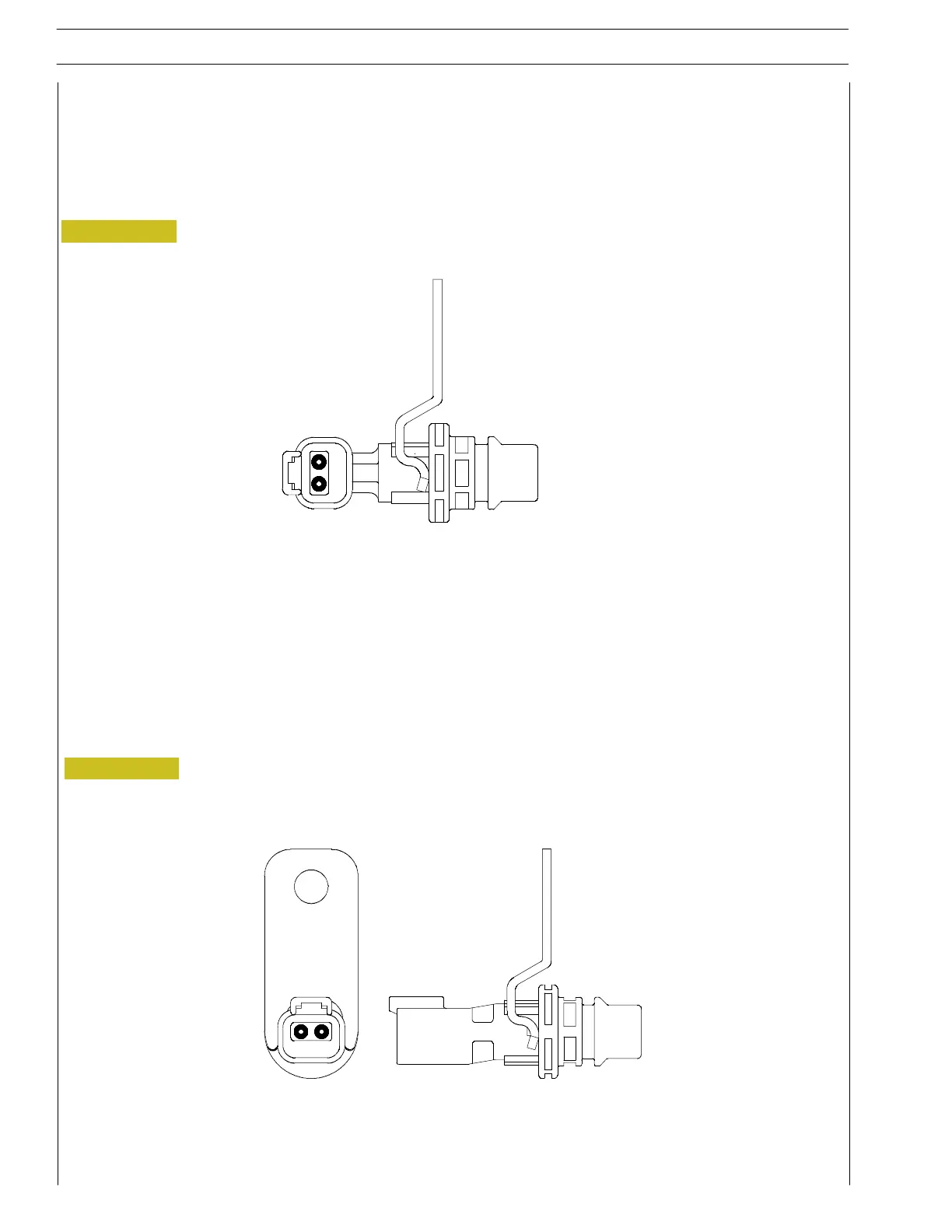
Figure 5
Figure 6
Engine speed/timing sensor on camshaft
This is an inductive t ype sensor and is positioned on the distribution shaft (reference 9, Figure 1).
It gen erat es signals that are o btain ed by means of the magnet ic flow lines th at c lose up through the holes on the gears th at are
keyed on the distribution shaft.. The signal that is generated and sent to the electronic unit that can calculate the injection moment.
The sensor must be assembled by tightening i t to torque 28 ± 7 Nm.
Tecnical view
48
SECTION 3 - INDUSTRIAL APPLICATION
VECTOR 8 ENGINES
Base - April 2006 Print P2D32V001E
 Loading...
