Figure 53
Figure 54
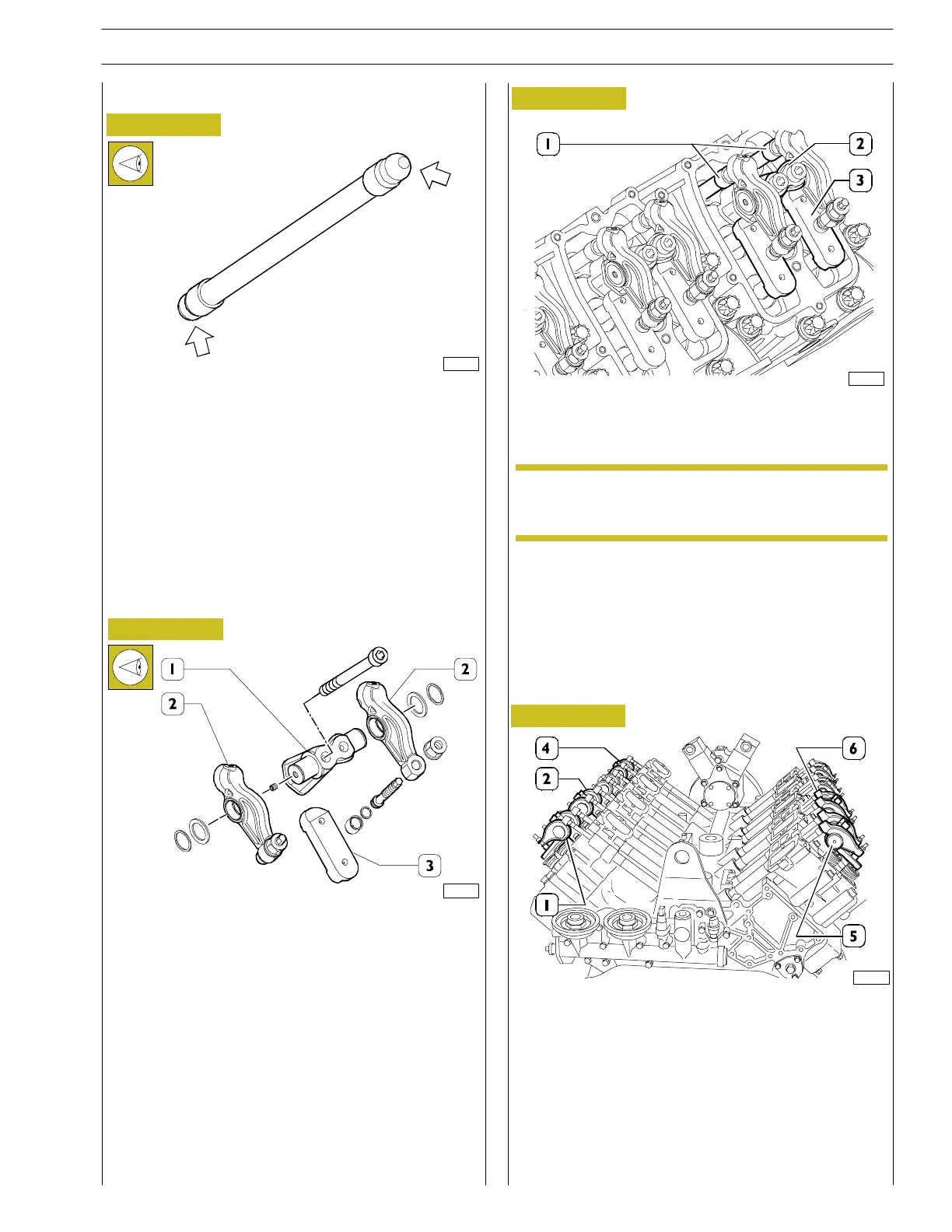
The valve pushrods must be free from distortion; the cup
seatings for the adjustment screws and th e ball ends locating
in the tappets (arrowed) must not show any signs of seizing
or wear; if they do, replace the rods.
Pushrods for inlet and exhaust valves are identic al and
therefor e interchangeable.
ROCKER ARM ASSEMBLY
ROCKER ARMS
JUMPERS
ROCKER ARM SUPPORT ROCKERS
- Chec k that the rocker arms (2), jumpers (3) and support
(1) show no sign of wear, scoring or seizu re.
Riscontrando anomalie, sostituire i particolari interessati.
- Check that the plug is assembled on the end of each
rocker—arm holding shaft.
RODS
- Install rods (1), rocker arm supports (2) with rocker arms
and bridges (3).
Figure 56
Make sure th at the bevelled side of the fall plate is
turned towards the inside of the engine.
Figure 55
- Make su re that cylinder 1 is in th e firin g order and that
cylin der 6 is balanced, then assemble roc ker—arm units
1-2-4-5 and 6.
- Check that the contact between the register and the
plate is centred and that the rods can turn freely.
82261
82721
82262
89828
NOTE
SECTION 3 - INDUSTRIAL APPLICATION
27
VECTOR 8 ENGINES
Print P2D32V001E Base - April 2006
 Loading...
