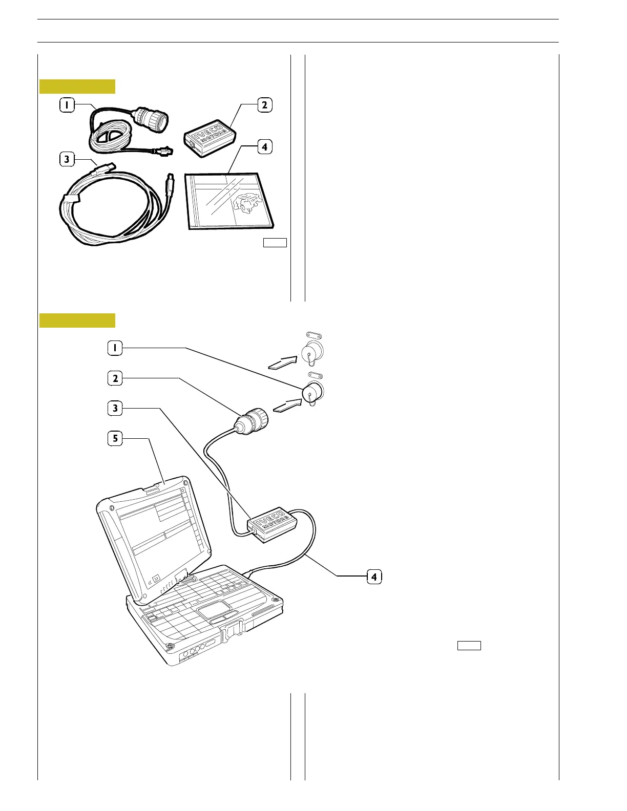
Connection procedures
- Unscrew plug (1) on switch box diagnosis conn ec t or.
- Connect the 25-pole connection of cable (2) on switch
box diagnosis connector.
- Connec t signal transc oding adapter (3) (Compact
Communication Adapter) to the other side of cable (2).
- Connect cable (4) to the opposite side of part (3).
- Connect the USB connection of PC (5) to the other end
of cable (4).
Figure 1
Diagnosis in terface kit for Vector motors
1. Cable connecting part 2 to diagnosis connector on
switch box - 2. Signal transcoding adapter (Compact
Communication Adapter) - 3. USB cable for PC -
4. In stallation CD
The CD must be installed on a personal computer (not
included in the kit) having following minimum c h aracteristics:
- Processor Intel Centrino I.IULV
- 512 MB Ram
-40GByteHD
- Internal modem 56 kbps V90
- Card LAN 100 BASE-TX/10-BASE-T
- 88 character keyboard
- Standard PC external interfaces
- Operating system Windows 2000 Professional.
Program installation must be performed following the
procedures that are contained on the CD in the kit.
Figure 2
LOCAL CONTROL
- ILC 99368543
connection
DIAGNOSE -
Troubleshooting
tool n. 99368550
connection
TROUBLESHOOTING WITH
TOOL 99368550
89757
89756
* The diagnostic connection (1) and the connector (2) vary depending on the application.
*
*
58
SECTION 3 - INDUSTRIAL APPLICATION
VECTOR 8 ENGINES
Base - April 2006 Print P2D32V001E
 Loading...
