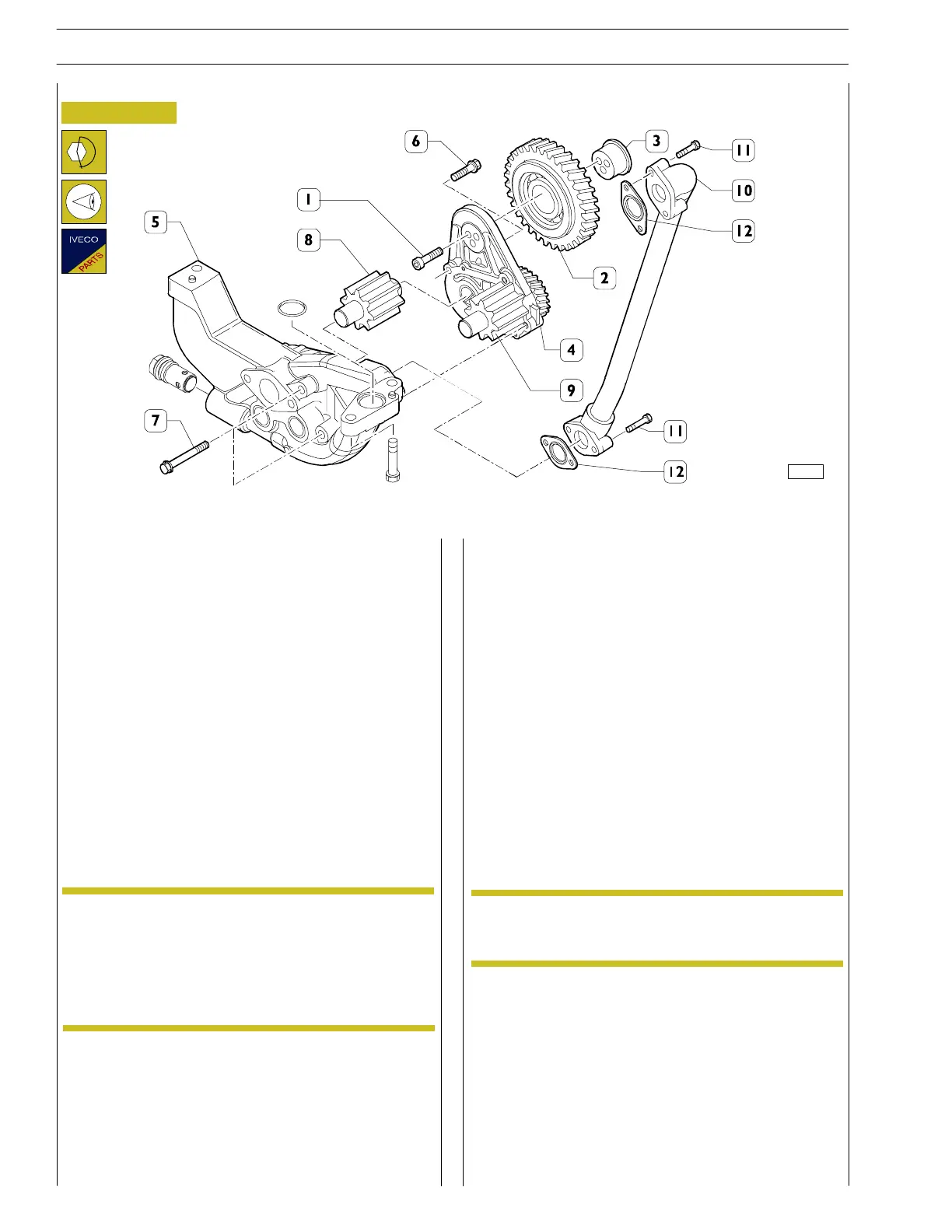
Figure 68
- Check the pump casing and the external gears. If there
are any visible signs of deterioration (cracks in the casing
or gear t eeth worn too muc h), ch ange th e whole part.
- Overhaul by unscrewing the screws (1) and removing
the gear (2) together with the ball bearing and pin (3).
- Check the bearing and the sliding surfaces of t he internal
cage of the bearing and of the pin (3) work properly.
- Then separate the pump cover (4) from the casing (5).
Unscrew the two screws (6) M8x30mm from the top of
the cover and the two screws (7) M8x80mm from the
casing side.
- Check the state of wear of the internal gears (8) an d (9).
In addition, check the gear (9) fitted stably on the cover
(4) turns freely.
Always change the seals (12) and O-rings.
Wear or poor rotation of the gear (9) require
changing the cover assembly (4) + (9) + (2) +(3)
supplied as spare parts already fitted.
The cover assembly also includes the bushing in
which the gear spindle (8) turns.
- Fit the gear (8) on th e cover assembly (4) and check its
rotation.
- Fit the cover together with the gears on the pump casing
(5).
- Fit the suction strainer on the pump with a new seal:
M8x1.25 screws (tightening torque 22—27 Nm).
- Fit the pump together with the suction strainer to the
crankcase.
The oil pump is secured with three M10x25mm
hexagonal—head screws with a tightening torque of
38—45 Nm, tightenin g the M8 screws to a torque of
22—27 Nm.
The suction strainer is secured to the cap for the central
support with two M8x25mm hexagon a l—head screws
with a torque o f 22—27 Nm.
- Fit the oil pipe (10) securin g it with the sc rews (11)
M8x45mm t o a tightening torque of 22—27 Nm.
- Lastly, fit the oil su mp with a new seal.
Tighten the M10 nuts on the stud bolts of the gearbox
to a torque of 38—45 Nm. The remaining M10x1.5x35
mm screws (24 in all) must be tightened to a torque of
38÷45 Nm.
82254
Oil pump
NOTE
NOTE
32
SECTION 3 - INDUSTRIAL APPLICATION
VECTOR 8 ENGINES
Base - April 2006 Print P2D32V001E
 Loading...
