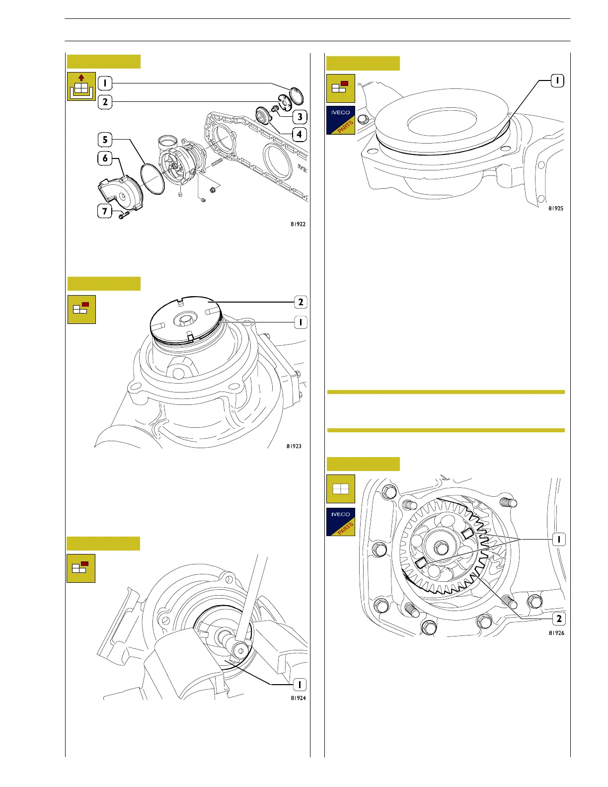
Figure 30
Figure 31
Figure 32
Figure 33
- After removing the pump, separate the components
from (1) to (7).
- Put the pump on the bench and, using the right pliers,
remove the snap ring (1).
- Remove the drive disc (2).
- Put in a vice and undo the cen tral s crew so as to be able
to remove the disc (1).
- Turn the pump and undo the three screws (7, Figure 30)
fixing the cover (6, Figure 30), complete with seal (1).
Fitting
- At the assembly stage, after changing the damaged parts,
assemble all the parts on the bench to complete the
pump.
Change th e seal on t he co ver. If the pump is not
chan ged, wash to remove any incru station.
Figure 34
- Fitting the complete pump on the gearbox must include
engaging the teeth (1) on the gear (2) on the drive disc.
- then screw the nuts onto the stud bolts on the gearbox.
- tightening torque 33 ÷ 40 Nm.
- then connect the water pipes.
NOTE
SECTION 3 - INDUSTRIAL APPLICATION
97
VECTOR 8 ENGINES
Print P2D32V001E Base - April 2006
 Loading...
